Linear gear shift mechanism for chainless vehicle

a technology of gear shift mechanism and chainless vehicle, which is applied in mechanical equipment, transportation and packaging, and gear shift mechanism, etc., can solve the problems of gear shift mechanism, large transmission loss, complex structure of the mechanism, etc., and achieve linear gear shift range wide and transmission loss small

Inactive Publication Date: 2019-01-01
MOTIVE POWER IND CO LTD
View PDF6 Cites 0 Cited by
  • Summary
  • Abstract
  • Description
  • Claims
  • Application Information

AI Technical Summary

Benefits of technology

[0003]In view of the aforesaid drawbacks of the prior art, the inventor of the present invention recognized room for improvement in the prior art and thus conducted extensive researches to therefore develop a linear gear shift mechanism for chainless vehicles, such that the linear gear shift mechanism for chainless vehicles is structurally simple and compact, has a wide linear gear-changing range, incurs little transmission loss, and never jerks while shifting gear.
[0016]Therefore, the linear gear shift mechanism for chainless vehicles according to the present invention is structurally simple and compact, has a wide linear gear-changing range, incurs little transmission loss, and never jerks while shifting gear.

Problems solved by technology

However, the front gear, rear gear, chain and gear shift mechanism are structurally intricate and bulky, have a narrow gear-changing range, incur much transmission loss, and tend to jerk while shifting gear.
However, the stepless gear shift mechanism has disadvantages, namely large volume of the grooved wheels and the V-shaped belt, and a narrow gear-changing range.

Method used


Image

  • Linear gear shift mechanism for chainless vehicle
  • Linear gear shift mechanism for chainless vehicle
  • Linear gear shift mechanism for chainless vehicle

Examples


Embodiment Construction

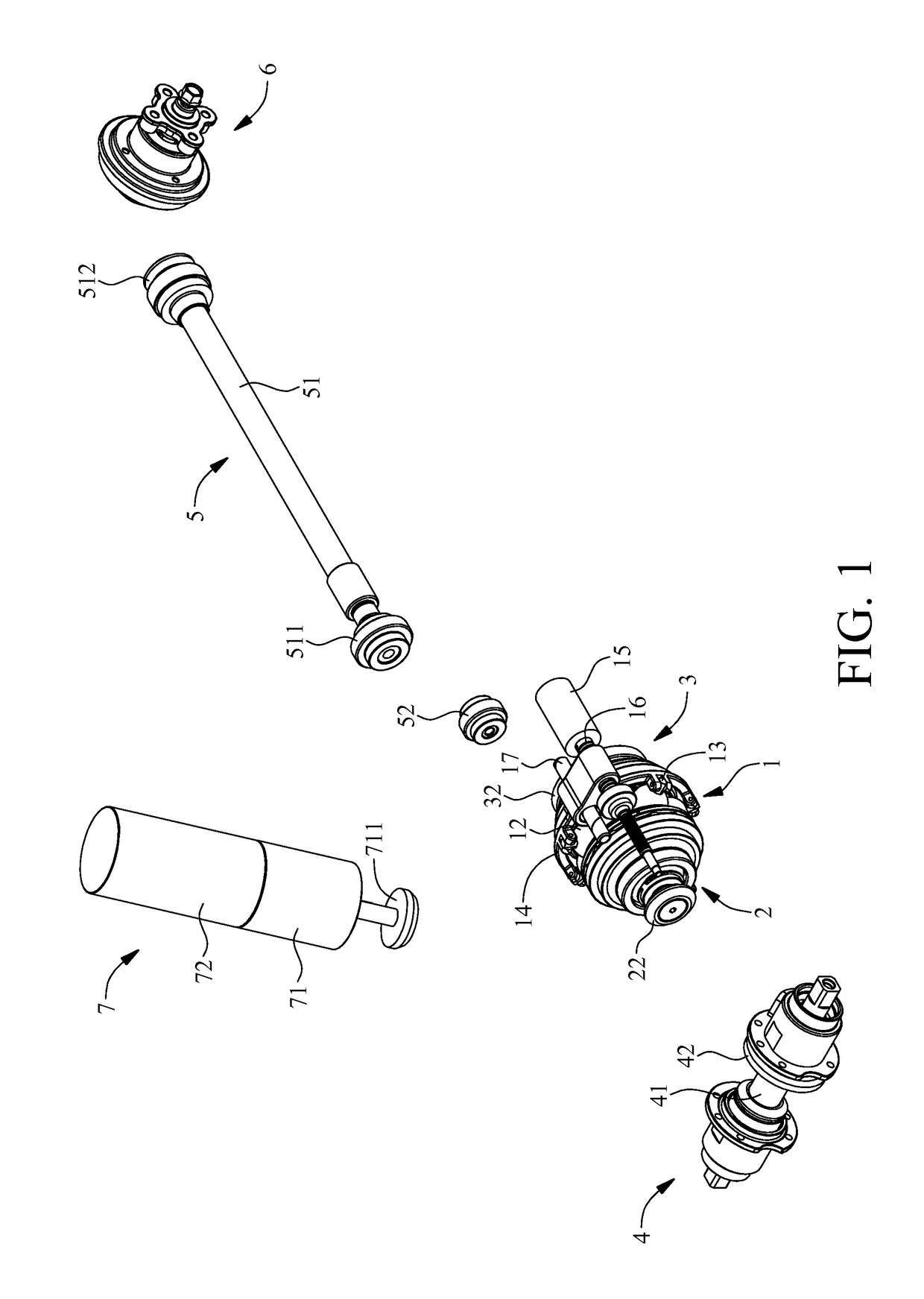
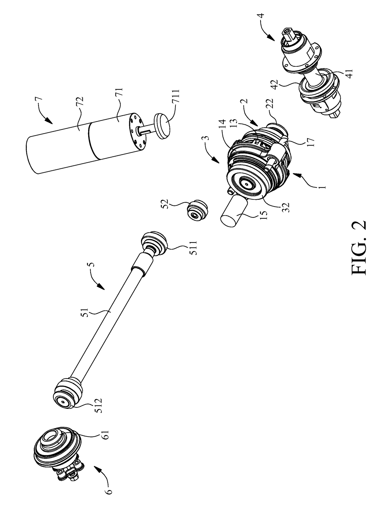
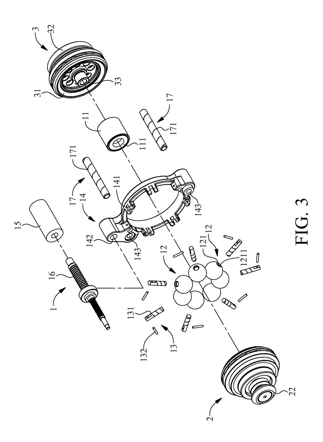
[0033]Referring to FIG. 1 through FIG. 14, to illustrate how transmission balls 12 and driving posts 13 operate, FIG. 5 and FIG. 10 show only how a transmission ball 12 and a driving post 13 operate, because the other transmission balls and driving posts also operate in the way shown in FIG. 5 and FIG. 10. The present invention provides a linear gear shift mechanism for chainless vehicles, which comprises a gear shift unit 1, an axial power input rotator 2, an axial power output rotator 3, a tread-required transverse power source 4, an axial power transfer portion 5 and a transverse power output portion 6. The gear shift unit 1 has a support rotator 11, a plurality of transmission balls 12 and a plurality of driving posts 13. The transmission balls 12 are spaced apart from each other by the same angle of circumference and movably disposed on the outer circumferential surface (shown in FIG. 5) or a lateral annular surface 112 (shown in FIG. 10) of the support rotator 11. The lateral ...


PUM


Abstract

A linear gear shift mechanism for chainless vehicles includes a gear shift unit having a support rotator, transmission balls and driving posts, with the transmission balls disposed in the support rotator, with a cylindrical receiving portion disposed on each transmission ball radially, with the driving posts disposed in the cylindrical receiving portions along radial direction of the support rotator and rotating from radial direction thereof to but not reach axial direction of the support rotator; an axial power input rotator having an inward-tilted power input annular surface; an axial power output rotator having an inward-tilted power output annular surface, with the transmission balls clamped between inward-tilted power input and output annular surfaces and support rotator; a tread-required transverse power source meshing with axial power input rotator; an axial power transfer portion meshing with axial power output rotator axially; a transverse power output portion meshing with axial power transfer portion.

Description

FIELD OF TECHNOLOGY[0001]The present invention relates to linear gear shift mechanisms for chainless vehicles and more particularly to a linear gear shift mechanism for chainless vehicles, which is structurally simple and compact, has a wide linear gear-changing range, incurs little transmission loss, and never jerks while shifting gear.BACKGROUND[0002]To adjust speed and tread easily, every tread-required means of transportation nowadays is equipped with a front gear, rear gear, chain and gear shift mechanism. However, the front gear, rear gear, chain and gear shift mechanism are structurally intricate and bulky, have a narrow gear-changing range, incur much transmission loss, and tend to jerk while shifting gear. Therefore, a stepless gear shift mechanism characterized by two grooved wheels operating in conjunction with a V-shaped belt is developed. However, the stepless gear shift mechanism has disadvantages, namely large volume of the grooved wheels and the V-shaped belt, and a ...

Claims


Application Information

Patent Timeline
Patent Type & Authority Patents(United States)
IPC IPC(8): F16H15/28B62M17/00B62M11/10B62M11/12B62M6/55
CPCB62M6/55B62M11/10B62M17/00B62M11/12F16H15/28B62M23/00
Inventor CHENG, HSIN-LINTENG, CHING-CHUNG
Owner MOTIVE POWER IND CO LTD
Why Eureka
Try Eureka