Optical fiber

a technology of optical fiber and fiber optics, applied in the field of optical fiber, can solve the problems of increasing transmission loss, and achieve the effect of small transmission loss and high failure strength

Inactive Publication Date: 2013-03-14
SUMITOMO ELECTRIC IND LTD
View PDF1 Cites 5 Cited by
  • Summary
  • Abstract
  • Description
  • Claims
  • Application Information

AI Technical Summary

Benefits of technology

[0009]The optical fiber according to the aspect of the present invention has the holes in the cladding around the core, and has a high failure strength and small transmission loss.

Problems solved by technology

Therefore, this optical fiber easily causes breakages starting from the wall surfaces of the holes, and transmission loss increases owing to Rayleigh scattering.

Method used


Image

  • Optical fiber
  • Optical fiber
  • Optical fiber

Examples


Embodiment Construction

[0015]Embodiments of the present invention will now be described with reference to the drawings. The drawings are for illustrative purposes, and are not intended to limit the scope of the present invention. To avoid redundancy of explanation, similar components are denoted by the identical reference numerals in the drawings. The dimensional ratios in the drawings are not necessarily correct.

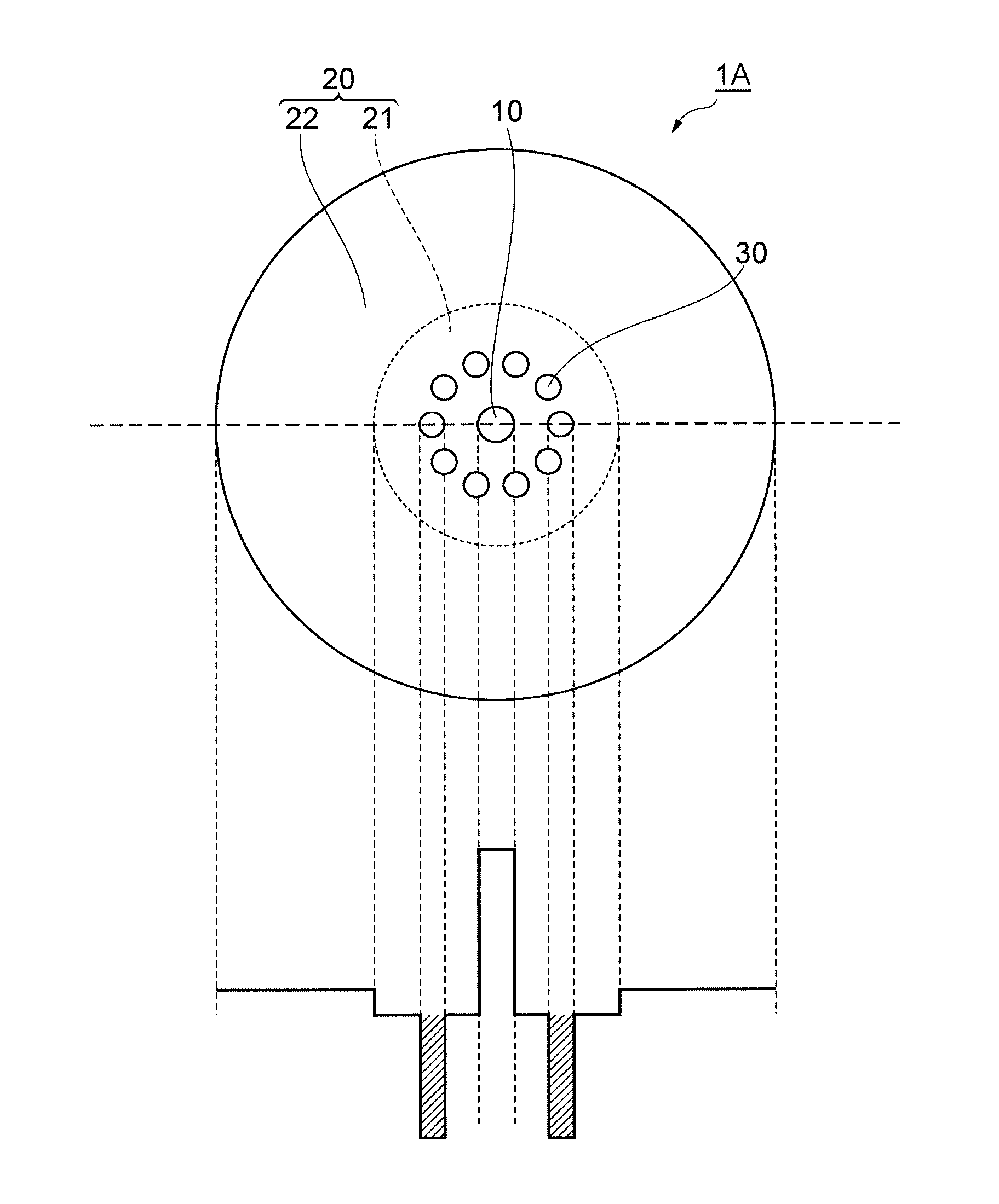
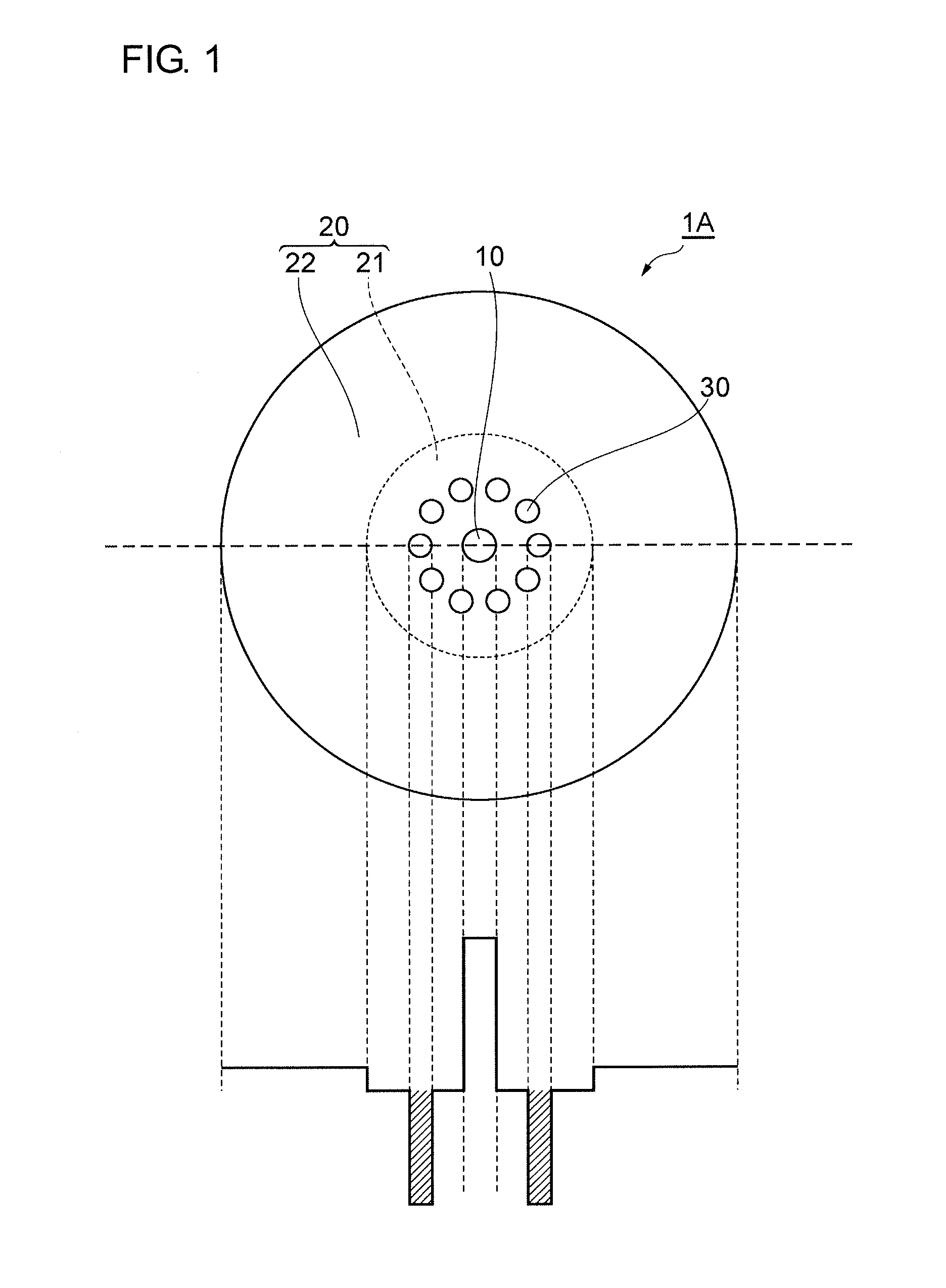
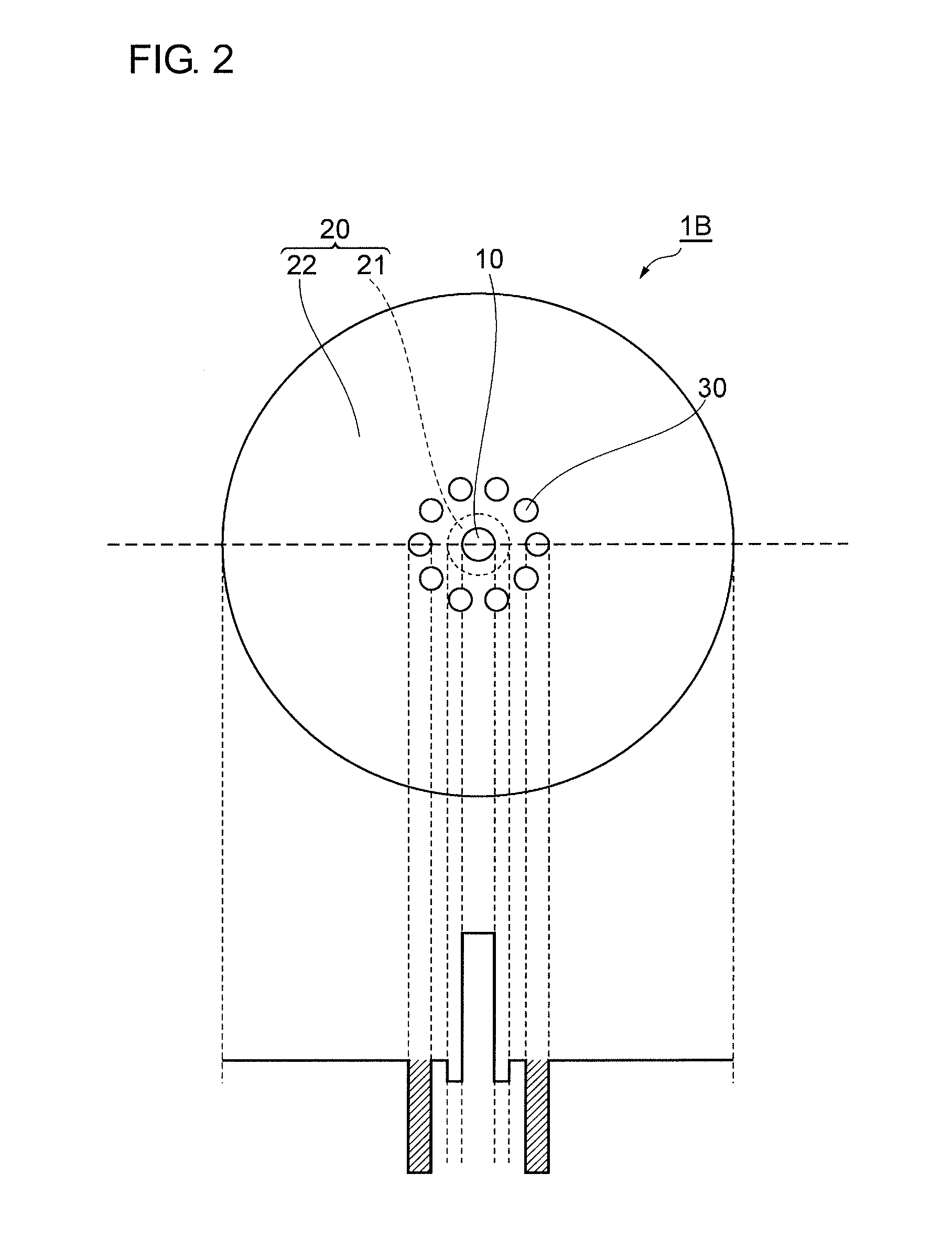
[0016]FIGS. 1 to 3 are conceptual diagrams illustrating the cross sectional structures and refractive index profiles of optical fibers 1A to 1C according to embodiments of the present invention. In each figure, the upper half shows the cross sectional structure and the lower half shows the refractive index profile along the broken line in the sectional view. The optical fibers 1A to 1C are called hole-assisted fibers (HAF). Each of the optical fibers 1A to 1C includes a core 10 made of glass, a cladding 20 made of glass that surrounds the core 10, and a plurality of holes 30 formed in the claddin...


PUM


Abstract

An optical fiber has a plurality of holes in a cladding around a core, and has a high failure strength and small transmission loss. The core is made of glass. The cladding surrounds the core, and the holes are formed in the cladding so as to extend along a central axis of the fiber. The holes are formed with constant intervals therebetween along a circle centered on the core, and each hole has a substantially circular cross section. The cladding is sectioned into two claddings. A residual stress in an inner region that is inside a circumcircle of the holes is a compressive stress.

Description

BACKGROUND OF THE INVENTION[0001]1. Field of the Invention[0002]The present invention relates to an optical fiber having a plurality of holes in a cladding around a core.[0003]2. Description of the Related Art[0004]Optical fibers having a plurality of holes that extend along the central axes of the fibers are known. Optical fibers having such holes are capable of having more properties compared to those of solid optical fibers that do not have the holes.[0005]Japanese Unexamined Patent Application Publication (Translation of PCT Application) No. 2005-538029 describes an optical fiber including an inner region having holes formed therein and an outer region around the inner region. The inner region is formed of a material having a higher softening point than that of the material of the outer region. With this structure, the holes are inhibited from distorting during drawing, and an optical fiber having desired properties can be manufactured. In this optical fiber, the material of the...

Claims


Application Information

Patent Timeline
Patent Type & Authority Applications(United States)
IPC IPC(8): G02B6/02
CPCG02B6/02366
Inventor NAGASHIMA, TAKUJITARU, TOSHIKIKUWAHARA, KAZUYA
Owner SUMITOMO ELECTRIC IND LTD
Why Eureka
Try Eureka