
End-effector force measurement drive circuit

a technology of force measurement and drive circuit, which is applied in the field of surgical devices, can solve the problems of unstable or inoperable surgical stapler, difficult to reduce the size of the device, and various kinds of electrosurgical devices that employ pcbs. to achieve the effect of preventing damage to the adapter

Active Publication Date: 2019-01-08
TYCO HEALTHCARE GRP LP
View PDF79 Cites 812 Cited by
  • Summary
  • Abstract
  • Description
  • Claims
  • Application Information

AI Technical Summary

Benefits of technology

The present invention is related to a surgical device that can measure the force applied by its motor during use. This is important because it allows for the detection and prevention of excessive loads that could damage the device. The method involves using a strain gauge and a drive circuit to directly measure the driving force in the device, and adjusting the force to prevent damage to the device.

Problems solved by technology

If the interconnections between the chip and the handle assembly are compromised, the chip could malfunction or data communications between the loading unit and the handle assembly could be disrupted, rendering the surgical stapler unstable or inoperable.
Various kinds of electrosurgical devices that employ PCBs have become thin and / or compact.
In some devices, the amount of space needed to accommodate the PCBs may make it difficult to reduce the size of the devices.
In some cases, PCB layouts large enough to accommodate the electrical components needed to provide desired functionality and / or performance may increase the overall size of the device and potentially hinder usability.
During a surgical procedure, when the end-effector assembly is clamping down on tissue, or firing, in some situations it may be unclear whether the end-effector assembly has hit a piece of cartilage, and the surgeon may not be sure if he wants to go further.
However, motor current measurements may not be entirely reliable, such as when the end-effector assembly has hit another staple line or encountered a malformed series of staples.

Method used


Image

  • End-effector force measurement drive circuit
  • End-effector force measurement drive circuit
  • End-effector force measurement drive circuit

Examples


Embodiment Construction

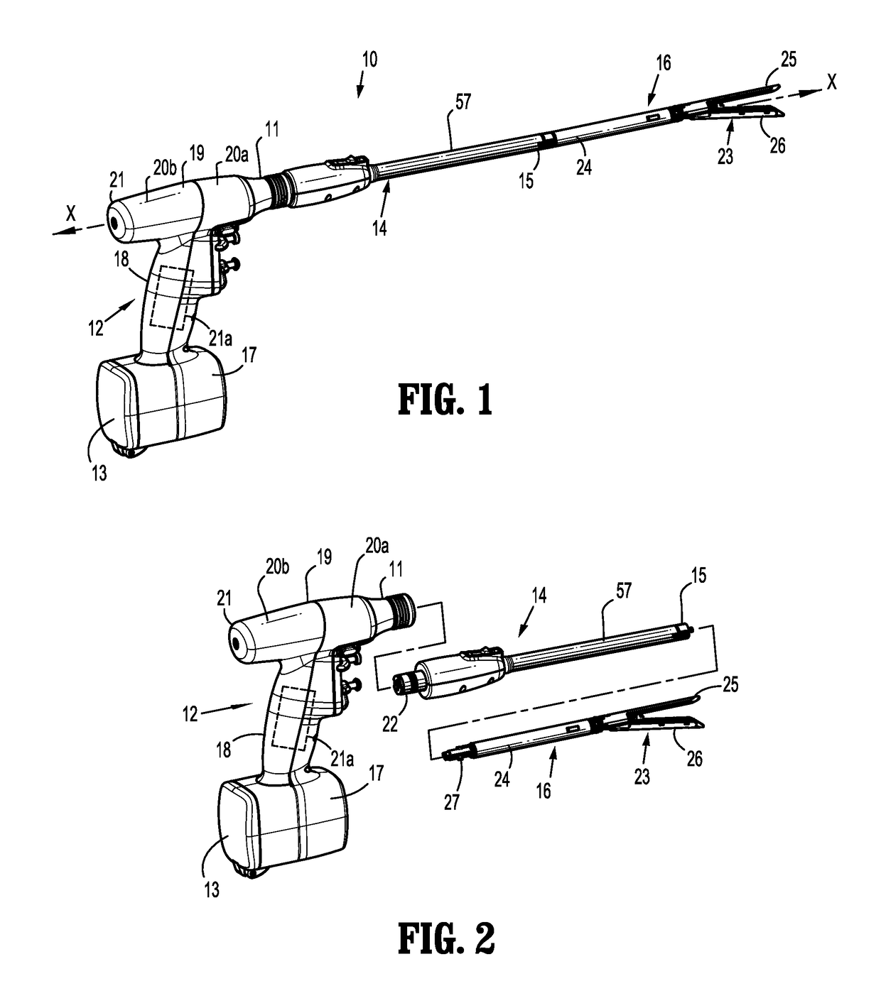
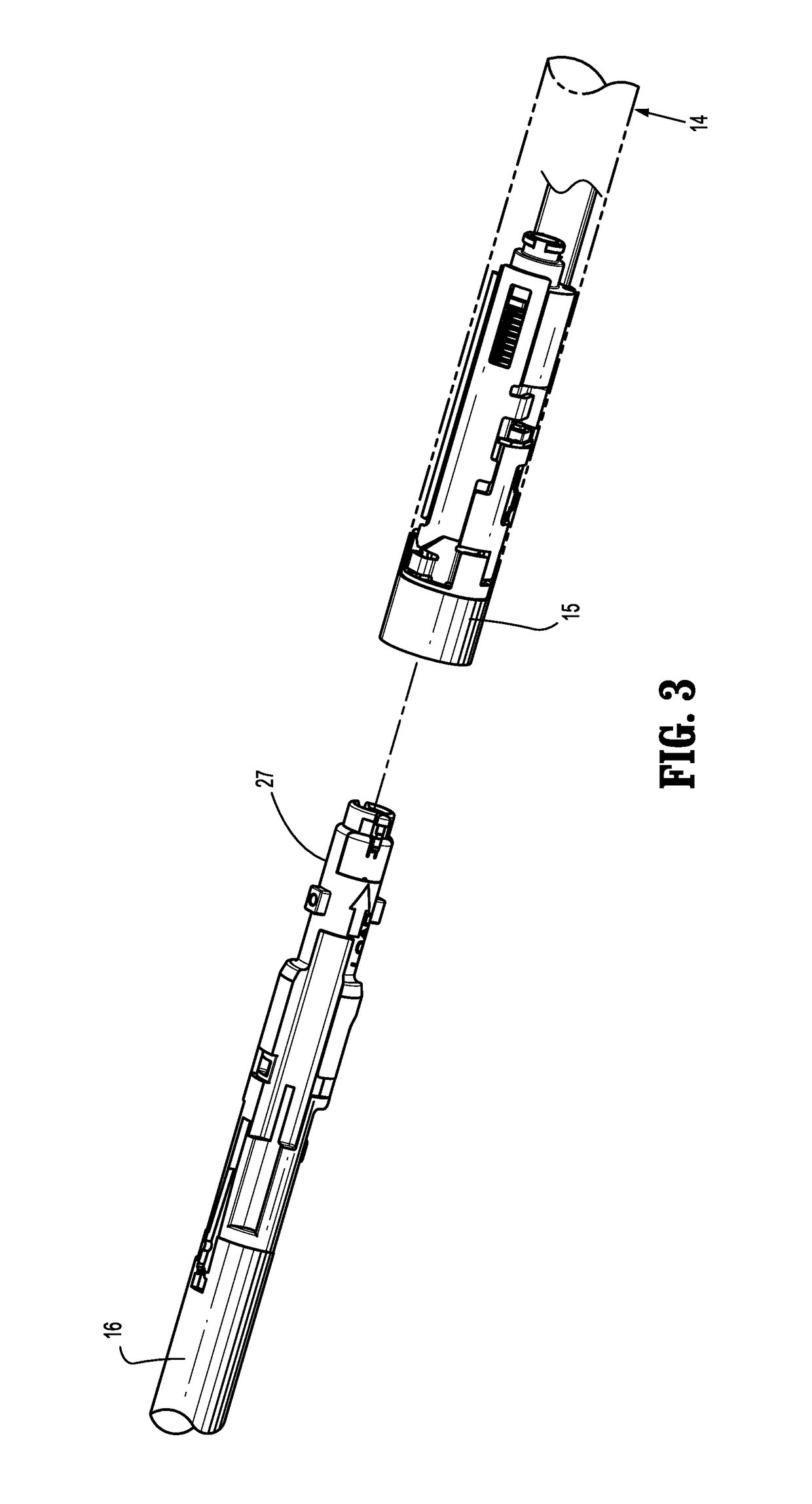
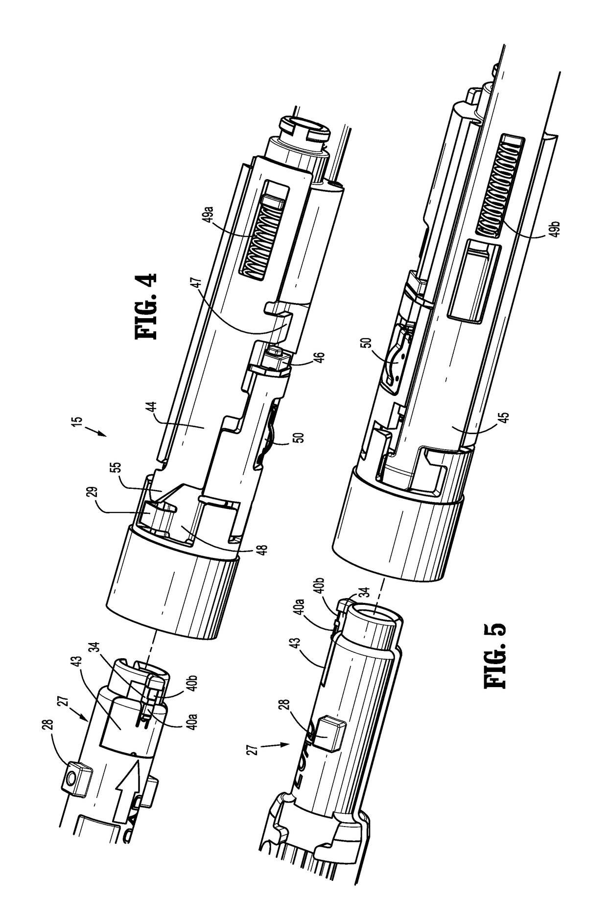
[0077]Hereinafter, embodiments of the presently-disclosed surgical instrument including an adapter configured with a strain gauge and a drive circuit and method of measuring a driving force in a surgical device are described with reference to the accompanying drawings. Like reference numerals may refer to similar or identical elements throughout the description of the figures. Particular embodiments of the present disclosure are described hereinbelow with reference to the accompanying drawings; however, it is to be understood that the disclosed embodiments are merely examples of the disclosure, which may be embodied in various forms. Well-known and / or repetitive functions and constructions are not described in detail to avoid obscuring the present disclosure in unnecessary or redundant detail. Therefore, specific structural and functional details disclosed herein are not to be interpreted as limiting, but merely as a basis for the claims and as a representative basis for teaching on...


PUM

PropertyMeasurementUnit
DC voltageaaaaaaaaaa
cut-off frequencyaaaaaaaaaa
driving forceaaaaaaaaaa

Abstract

A surgical instrument for applying fasteners includes a drive motor, a replaceable loading unit having an end-effector assembly, and an adapter configured to releasably couple a replaceable loading unit to the drive motor. The adapter includes a strain gauge having a drive circuit coupled thereto. The strain gauge and the drive circuit are configured to directly measure a driving force in the adapter.

Description

CROSS-REFERENCE TO RELATED APPLICATIONS[0001]This application claims the benefit of and priority to U.S. Provisional Patent Application No. 61 / 988,342, filed May 5, 2014, the entire disclosure of which is incorporated by reference herein.BACKGROUND[0002]1. Technical Field[0003]The present disclosure relates to surgical devices having a reusable handle assembly and removable and replaceable components. More particularly, the present disclosure relates to an end-effector force measurement drive circuit suitable for use in a surgical instrument for applying fasteners.[0004]2. Discussion of Related Art[0005]Powered surgical instruments for use in endoscopic procedures are known. Typically, such instruments include a reusable handle assembly, and a replaceable and generally disposable component sometimes referred to as single use loading unit or SULU. An adapter assembly connects the loading unit, which can include an end effector for interacting with tissue, to the handle assembly. In t...

Claims


Application Information

Patent Timeline
Patent Type & Authority Patents(United States)
IPC IPC(8): G01L5/00A61B17/072A61B90/98A61B17/00A61B90/00
CPCG01L5/0028A61B17/07207A61B90/98A61B2090/064A61B2017/00473A61B2017/07278A61B2017/00398G01L1/22A61B2017/0046A61B2017/00017
Inventor COLLINS, ETHANHRYB, JOHNCALDERONI, ANTHONYPANTAZIS, JOHN
Owner TYCO HEALTHCARE GRP LP
Learn More