Control device for a hydraulic cylinder unit having optimized linearization

Active Publication Date: 2019-01-08
PRIMETALS TECH GERMANY
View PDF4 Cites 1 Cited by
  • Summary
  • Abstract
  • Description
  • Claims
  • Application Information

AI Technical Summary

Benefits of technology

The patent describes a problem in hydraulic systems where the pressure on both sides of a piston is used in the hydraulic system and in the linearization process. However, the linearization is delayed by the valve control unit, resulting in a lower increase in force than expected. This affects the control's dynamics. A solution is proposed to address this issue and ensure a more stable linearization process.

Problems solved by technology

However, practice has shown that this procedure is also still afflicted by disadvantages.
One disadvantage consists of the working pressures on both sides of the piston being used both in the hydraulic system and in the linearization.
A further disadvantage consists of a manipulated variable, which moves the piston of the hydraulic cylinder unit at a certain speed, being modulated by changes in force (changes in pressure) by way of the linearization.
Consequently, the control is destabilized.

Method used


Image

  • Control device for a hydraulic cylinder unit having optimized linearization
  • Control device for a hydraulic cylinder unit having optimized linearization
  • Control device for a hydraulic cylinder unit having optimized linearization

Examples


Embodiment Construction

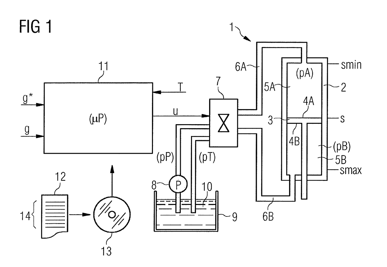
[0038]In accordance with FIG. 1, a hydraulic cylinder unit 1 comprises a hydraulic cylinder 2, in which a piston 3 is mounted in a movable fashion. The piston 3 is movable within the hydraulic cylinder 1 between a minimum position smin and a maximum position smax. Thus, it is at an actual position s, which lies between the minimum position smin and the maximum position smax, at all times.

[0039]The piston 3 has a first working face 4A and a second working face 4B. Each working face 4A, 4B faces a corresponding working volume 5A, 5B.

[0040]The working volumes 5A, 5B are hydraulically connected to a hydraulic pump 8 and a hydraulic reservoir 9 via hydraulic paths 6A, 6B and a valve control unit 7. The hydraulic paths 6A, 6b extend from the respective working volume 5A, 5B to the valve control unit 7.

[0041]A certain volume of a hydraulic liquid 10 is situated in the hydraulic path 6A when the piston 3 is situated in its minimum position smin. This volume is the minimum amount of hydrauli...


PUM


Abstract

A controller (15) which receives a target value (g*) related to a piston (3) of the hydraulic cylinder unit (1) and an actual value (g) related to the piston (3) of the hydraulic cylinder unit (1). On the basis of the difference (δg) of the values, the controller determines a provisional manipulated variable (u′). A linearization unit (17) downstream of the controller (15) multiplies the provisional manipulated variable (u′) by a linearization factor (F) and outputs the product to a valve control unit (7) as a final manipulated variable (u) such that the actual value (g) is brought toward the target (g*) at an adjustment speed. On the basis of working pressures (pA, pB) on both sides of the piston (3) and / or working pressures (pP, pT) on the feed side and on the outflow side of the valve control unit (7) and a target piston force (FKL) to be applied by the piston (3), the linearization unit (17) determines target values (pA*, pB*) for the working pressures (pA, pB). The linearization unit determines the linearization factor (F) dynamically as a function of an actual position(s) of the piston (3), the target values (pA*, pB*), and the working pressures (pP, pT) on the feed side and on the outflow side of the valve control unit (7).

Description

CROSS-REFERENCE TO RELATED APPLICATIONS[0001]The present application is a 35 U.S.C. §§ 371 national phase conversion of PCT / EP2015 / 056412, filed Mar. 25, 2015, which claims priority of European Patent Application 14165962.3, filed Apr. 25, 2014, the contents of which are incorporated by reference herein. The PCT International Application was published in the German language.[0002]The present invention proceeds from a control device for controlling a hydraulic cylinder unit,[0003]wherein the control device comprises a controller having an input side which receives a setpoint variable related to a piston of the hydraulic cylinder unit and an actual variable related to the piston of the hydraulic cylinder unit and establishes a preliminary manipulated variable for a valve control unit of the hydraulic cylinder unit on the basis of the difference between setpoint variable and actual variable,[0004]wherein a linearization unit is disposed downstream of the controller, the linearization u...

Claims


Application Information

Patent Timeline
IPC IPC(8): G05B11/38G05B11/36G05D7/06
CPCG05B11/38G05D7/0635G05B11/36G05D3/20
Inventor TAUTZ, WILFRIED
Owner PRIMETALS TECH GERMANY
Why Eureka
Try Eureka