Method, device and system for simulating shadow images

a technology of shadow images and devices, applied in the direction of image analysis, 2d-image generation, processor architecture/configuration, etc., can solve the problems of limited system memory, slow and time-consuming techniques according to the prior art, and inability to implement interactive applications

Active Publication Date: 2019-01-29
3MENSIO MEDICAL IMAGING
View PDF9 Cites 10 Cited by
  • Summary
  • Abstract
  • Description
  • Claims
  • Application Information

AI Technical Summary

Benefits of technology

[0019]The shadow image, instead of being calculated from the 3D volumetric data, is advantageously calculated from the 3D mesh data that resulted from segmentation of the 3D data. This decreases the need for transferring and processing large data volumes of 3D volumetric image data thus allowing this technique to be used on a wide range of (mobile) devices that are equipped with less memory. The surface meshes are small enough to be easily transferred over the internet (i.e. mail) and stored on these devices, which is typically a lot harder with 3D volumetric data.
[0023]Angiographic simulation according to embodiments herein can be used to get a preview of what the patient's blood vessels will look like when examined using X-rays, for instance in a catheterization laboratory or during procedure preparation to help to choose the best viewing perspective of the X-ray scanner for the procedure. The simulation does not need to be exact: the grey levels cannot be entirely predicted as they depend on (amongst others) the amount of contrast agent injected during the procedure. It is however advantageous if they show the effect when vessels overlap occurs.

Problems solved by technology

Such calculation of pixel intensity from 3D voxel dataset to simulate a 2D shadow image requires access to a relatively large amount of data and takes a significant amount of computer processing power that might be time-consuming even when done in parallel on a graphic processing unit (GPU).
For acceptable performance on low-end hardware, and in general where there is limited calculation power and lack of possible use of parallel calculations, e.g. no, or limited GPU, the technique according to the prior art will be slow and impractical for interactive application.
For instance, on mobile devices, the processing power and the amount of system memory are limited, and the (wireless) network bandwidth to transfer large 3D volumetric dataset to the device may not be feasible.
Even more, when dynamic visualization is required and all 3D volumetric image data over time is available, generating a dynamic simulated 2D X-ray angiographic image, which simulated cardiac motion at an acceptable framerate, may not be feasible with the available computation power.
The surface meshes are small enough to be easily transferred over the internet (i.e. mail) and stored on these devices, which is typically a lot harder with 3D volumetric data.

Method used


Image

  • Method, device and system for simulating shadow images
  • Method, device and system for simulating shadow images
  • Method, device and system for simulating shadow images

Examples


Embodiment Construction

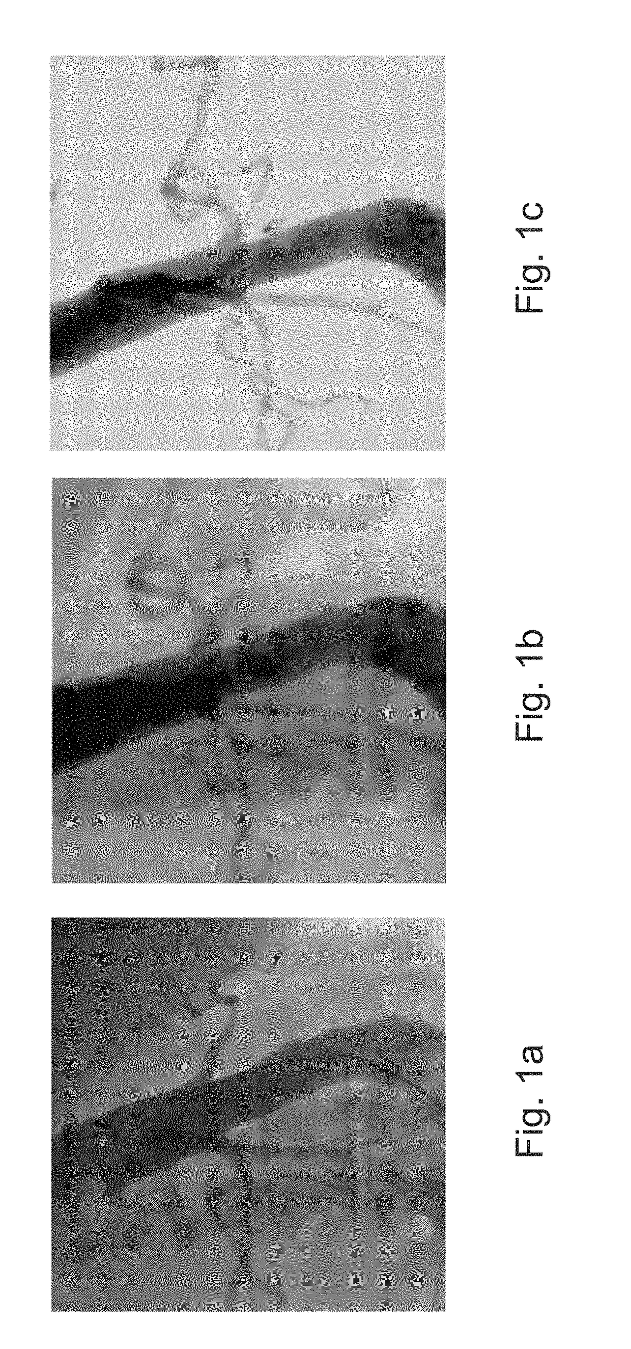
[0051]An angiographic image visualizes the attenuation of an X-ray beam through an object under scrutiny. No attenuation (vacuum, air) is rendered white, high attenuation (bone, metal, contrast agent) is rendered as dark grey or black. The longer the X-ray travels through highly absorbing material, the darker the image becomes. An example of such an angiographic image is shown in FIG. 1a.

[0052]FIG. 6 is a functional block diagram of an exemplary single plane angiographic system capable of obtaining angiographic images. The system includes an angiographic imaging apparatus 112 that operates under commands from user interface module 116 and will provide data to data processing module 114. The single plane angiographic imaging apparatus 112 captures a two-dimensional X-ray image of the vessel organ of interest for example in the postero-anterior (PA) direction. The single plane angiographic imaging apparatus 112 typically includes an X-ray source and detector pair mounted on an arm of...


PUM


Abstract

A method is provided for simulating two-dimensional (2D) shadow images of an object (particularly an asymmetrical object), which comprises:a) obtaining a representation of the surface of said object;b) inputting a perspective viewing direction defining a virtual path line;c) calculating intersections between the virtual path line and the surface of the object;d) calculating the distance between couples of consecutive intersections;e) calculating simulated beam intensity attenuation between such couples of consecutive intersections from an input parameter related to the attenuation coefficient of the object and the distance as calculated in d); andf) displaying the simulated beam intensity attenuation as pixel brightness in a grey or color scale in the form of a shadow image.A corresponding device, system and computer program are also disclosed.

Description

CROSS-REFERENCE TO RELATED APPLICATIONS[0001]The present disclosure claims priority from EP Patent Application No. EP16182125, filed on Aug. 1, 2016, herein incorporated by reference in its entirety.BACKGROUND OF THE INVENTION1. Field[0002]The present disclosure relates to a method, device and system for calculation and visualization of shadow images of an object of interest.2. State of the Art[0003]Angiography is a commonly used imaging modality performed to image and diagnose diseases of the blood vessels of the body, including the brain and the heart. In cardiology and radiology two-dimensional (2D) angiography is a medical imaging technique used to visualize the inside, or lumen, of blood vessels and organs of the body, with particular interest in the arteries, veins, and the heart chambers by injecting a radio-opaque contrast agent into the blood vessel and imaged using X-ray based techniques such as angiography or fluoroscopy. Radiologists, cardiologists and vascular surgeons ...

Claims


Application Information

Patent Timeline
Patent Type & Authority Patents(United States)
IPC IPC(8): G06T1/20G06T7/10G06T11/00G06T15/50G06T15/60
CPCG06T15/60G06T11/008G06T15/506G06T1/20G06T2211/404G06T2207/10081G06T2207/30101G06T2210/41G06T7/10
Inventor DE VAAN, JANHEIL, PETER
Owner 3MENSIO MEDICAL IMAGING
Why Eureka
Try Eureka