Supercharge Your Innovation With Domain-Expert AI Agents!

Water flow regulator

a flow regulator and flow valve technology, applied in water installations, water resource protection, construction, etc., can solve the problems of reducing the outlet volume, bad water saving effect, and poor volume stability, and achieve the effect of reducing pressure loss, high volume, and reducing impacting nois

Active Publication Date: 2019-02-05
XIAMEN SOLEX HIGH TECH IND CO LTD
View PDF11 Cites 0 Cited by
  • Summary
  • Abstract
  • Description
  • Claims
  • Application Information

AI Technical Summary

Benefits of technology

[0007]the water stop ring (400) is supported on the annular seat (300) to surround and fit to the central base (220), so that the flowing area of the flowing clearance is adjustable by the water pressure so as to save water.
[0019]1. the deflecting annular wall is configured, the flowing clearance is disposed above the deflecting annular wall so that water flows out of the flowing clearance and then directly impacts the deflecting annular wall, it can reduce the pressure loss when water flows from the flowing clearance to the diversion holes, even in low pressure, it can achieve high volume and reduce impacting noise. The water stop ring is supported on the annular seat and surrounding and fitting to the central base, when water pressure acts on the elastic water stop element, the elastic water stop element deforms inwardly radically, it has well water saving effect and high stable flow volume.
[0020]2. the diversion device and the annular seat can be two separated components, the structure has advantages that when to develop products with different volume, it can just develop different diversion devices, and it can adjust the arrangement and size of the diversion holes as the different volume classes needed, so that it can achieve better outlet effect of the water type of the outlet devices.

Problems solved by technology

In this application, firstly, water flows out of the diversion holes and directly vertically impacts the bottom plate, then flows out of the diversion passages, as water from the diversion holes directly vertically impacts the bottom plate, it greatly decreases the water pressure, resulting in reducing of outlet volume, and it also produces noise; secondly, the elastic water stop element is sleeved on the protrusion, when water pressure acts on the elastic water stop element, as the inner side of the elastic water stop element is limited that the elastic water stop element is pressed and deformed outwardly in the radial direction, resulting in bad water saving effect and bad volume stability. at the same way, CN202139650U, CN1761791A, CN104047336A has the same problem as CN102926437B.

Method used


Image

  • Water flow regulator
  • Water flow regulator
  • Water flow regulator

Examples


Embodiment Construction

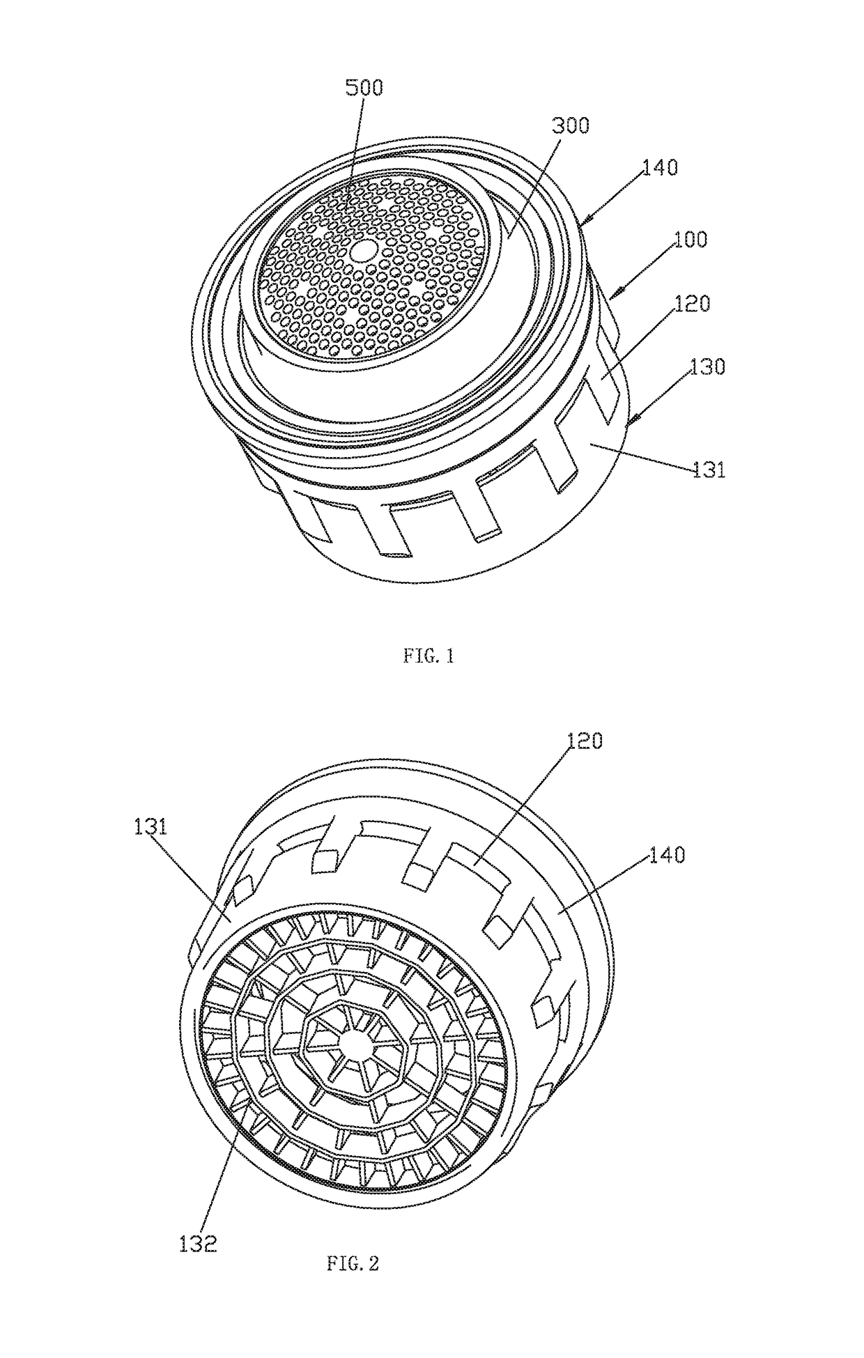
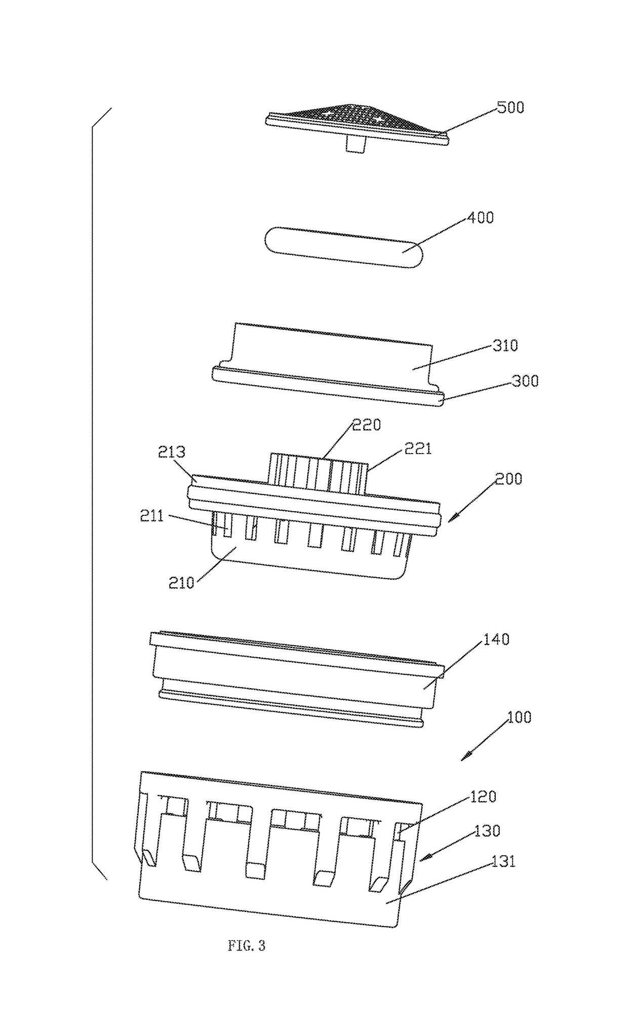
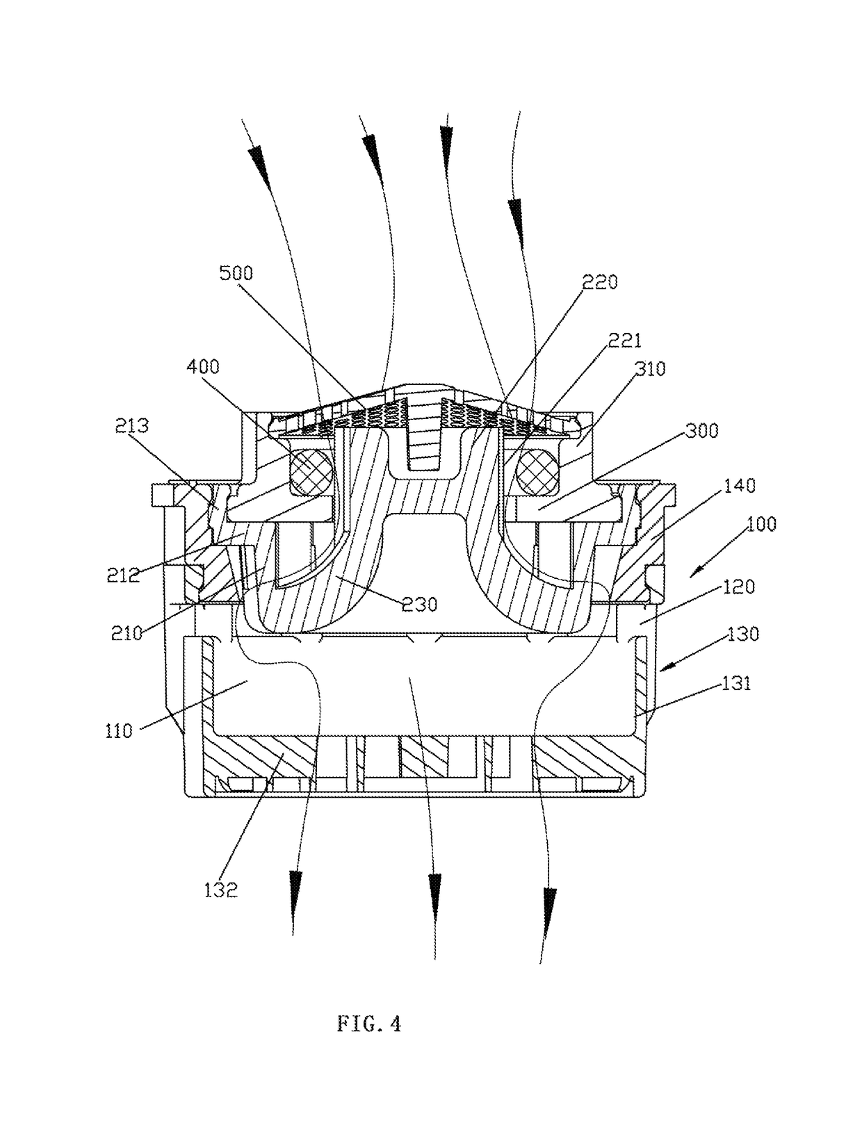
[0030]Referring to FIGS. 1-8, the flow regulator comprises a housing portion 100, a diversion device 200 assembled in the housing portion 100, an annular seat 300, an elastic water stop ring 400 and a filter 500.

[0031]The housing portion 100 comprises a housing 130 and a fixing ring 140, the housing 130 comprises an outer wall 131 and an inserting element 132 fixedly connected at the bottom portion of the outer wall 131, the inserting element 132 is a grid outlet mesh, the outer wall 131 is disposed with a plurality of suction passages 120 annularly arranged running through the inside and outside of the outer wall 131, the fixing ring 140 is fixedly connected to the upper portion of the outer wall 131, the housing portion 100 is disposed with a mutation chamber 110.

[0032]The diversion device 200 comprises a periphery wall 210, a central base 220 in the periphery wall 210 and a deflecting annular wall 230 fixedly connecting the periphery wall 210 and the central base 220, the upper p...


PUM


Abstract

A flow regulator includes a housing portion, a diversion device, an annular seat and an elastic water stop ring. The annular seat, the diversion device and the housing portion are fixedly assembled together. The diversion device includes a periphery wall disposed with diversion holes, a central base within the periphery wall and a deflecting annular wall fixedly connecting the periphery wall and the central base. The external periphery surface of the deflecting annular wall is gradually larger downwardly from the central base to the periphery wall. The central base at least partly extends out of the internal hole of the annular seat. A water flow clearance is formed between the central base and the hole wall of the internal hole of the annular seat. The water flow clearance is disposed above the deflecting annular wall so that water flows out of the flowing clearance and onto the deflecting annular wall.

Description

FIELD OF THE INVENTION[0001]The present invention relates to a flow regulator.BACKGROUND OF THE INVENTION[0002]An integrated flow regulator is published in Chinese patent database with announce number CN102926437B, it comprises a main body, a mutation chamber, a fixed ring and a diversion device. Water from the outsider flows firstly through the filter, then through the diversion holes, and through the diversion passages finally to the mutation chamber, which sucks air in due to the negative pressure according to Venturi effect, water and air mix and flow out of the outlet; the elastic water stop piece directly faces to the water from the filtering portion, under the action of the water pressure, it expands at the diversion holes to change the effective section area of the diversion holes. In this application, firstly, water flows out of the diversion holes and directly vertically impacts the bottom plate, then flows out of the diversion passages, as water from the diversion holes d...

Claims


Application Information

Patent Timeline
Patent Type & Authority Patents(United States)
IPC IPC(8): E03C1/084E03C1/08
CPCE03C1/084E03C1/08Y02A20/411E03C2201/40
Inventor HUANG, FEILONGZHAO, GUOSONGCHEN, WENXING
Owner XIAMEN SOLEX HIGH TECH IND CO LTD
Features
  • R&D
  • Intellectual Property
  • Life Sciences
  • Materials
  • Tech Scout
  • Unparalleled Data Quality
  • Higher Quality Content
  • 60% Fewer Hallucinations
Learn More