Weep screed

Active Publication Date: 2019-02-05
DUFFY FRANK L +1
View PDF25 Cites 27 Cited by
  • Summary
  • Abstract
  • Description
  • Claims
  • Application Information

AI Technical Summary

Benefits of technology

[0004]It is an object of the invention to enhance d

Problems solved by technology

Unfortunately, these energy saving measures inhibit the ability of the exterior walls to breath and ultimately dry.
Failure of an exteri

Method used


Image

  • Weep screed
  • Weep screed
  • Weep screed

Examples


Embodiment Construction

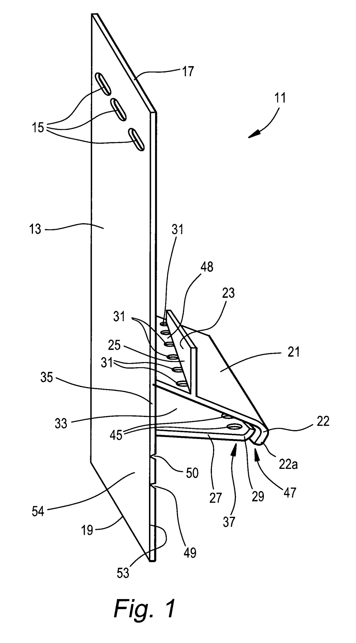
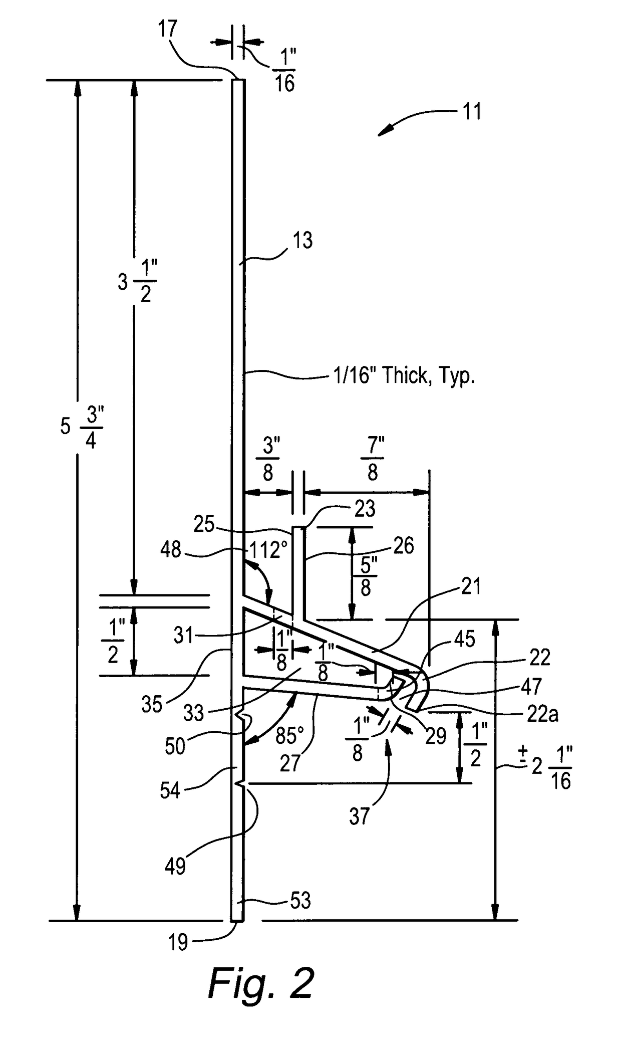
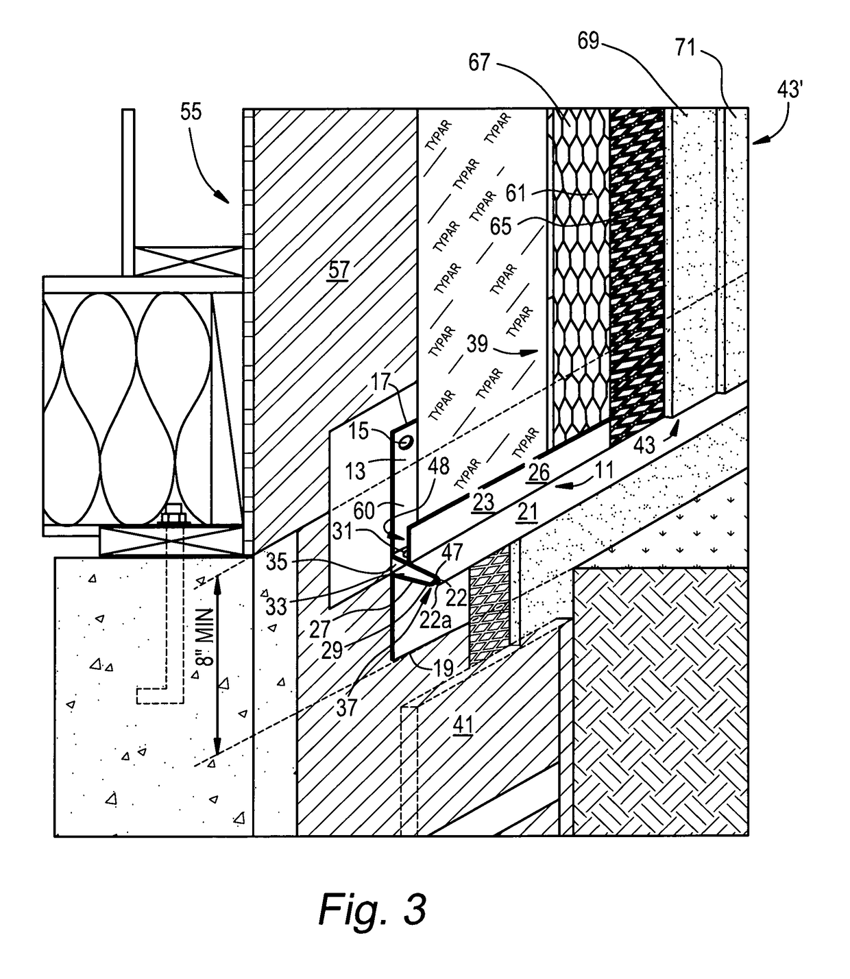
[0035]Turning now to the drawings, there is shown in FIGS. 1-5 a first embodiment of the inventive weep screed 11. Preferably, the inventive weep screed 11 is designed to be mounted on the bottom of an exterior wall of a building at foundation level to help support the exterior cladding (e.g., stucco) of the exterior wall resting on the weep screed 11, provide a water barrier between the exterior wall and the foundation of the building, direct water that penetrates the exterior cladding from outside the building and drains downwardly in the exterior cladding, or between the exterior cladding and a weather resistant barrier (such as Tyvek) wrapped onto the backing wall of the exterior wall, to the weep screed 11 to flow downwardly along the primary ground flange 21 to the drip line 22a and then fall away from the building, permit moisture located between the weather resistant barrier (such as Tyvek), that is wrapped onto the backing wall of the exterior wall, and the exterior claddin...


PUM


Abstract

A convective weep screed for draining water that penetrates exterior cladding of an exterior wall of a building away from the building and for removing moisture located in the space between the weather resistant barrier of the wall and the exterior cladding and for providing ventilation to the space between the weather resistant barrier and the exterior cladding. The weep screed provides a pathway to the space between the weather resistant barrier and the exterior cladding to permit water/moisture/moisture vapor that collects there to drain therefrom and to permit air to gain access to said space, thereby providing an uninterrupted pathway for air to ventilate and dry said space.

Description

FIELD OF THE INVENTION[0001]This invention relates to weep screed for draining water that penetrates exterior cladding, such as stucco, of an exterior wall of a building away from the building, and more particularly is concerned with weep screed for draining water that penetrates exterior cladding of an exterior wall of a building away from the building and for removing moisture located in the space between the weather resistant barrier (such as Tyvek), which is wrapped onto the backing wall of the exterior wall, and the exterior cladding, and for providing ventilation to the space between the weather resistant barrier (such as Tyvek) and the exterior cladding.BACKGROUND OF THE INVENTION[0002]In the building construction art, it has been a requirement under the Uniform Building Code since 1973 to use a weep screed at the base (that is, the foundation plate line) of exterior walls of a building to help support exterior cladding (e.g., stucco) of the exterior walls, to provide a water...

Claims


Application Information

Patent Timeline
IPC IPC(8): E04B1/70
CPCE04B1/7038E04B1/7076E04F13/007E04F13/06E04F2013/065
Inventor DUFFY, FRANK L.CHRISTOPHER, JR., RONALD L.
Owner DUFFY FRANK L
Why Eureka
Try Eureka