Ball stud strategy for hand-replaceable components requiring electric power

a technology of hand-replaceable components and ball studs, which is applied in the direction of spark plugs, electrical control, coupling device connections, etc., can solve the problems of requiring the removal of the engine cover completely, the challenge of hiding the wiring necessary to energize the illuminated badging, and the wires typically remain exposed and unattractive, etc., to achieve easy removal and reinstallation, and the effect of easy removal

Active Publication Date: 2019-02-05
FORD GLOBAL TECH LLC
View PDF19 Cites 0 Cited by
  • Summary
  • Abstract
  • Description
  • Claims
  • Application Information

AI Technical Summary

Benefits of technology

[0008]The disclosed inventive concept overcomes the problems associated with current approaches to providing power to removable vehicle components while making the component easy to remove and reinstall. The disclosed inventive concept provides a conductive ball stud fastener arrangement that provides energy to the electrified component having an electrified element such as an illuminated badge while also enabling the component to be readily removed and reinstalled as may be needed to provide proper servicing to the underlying substrate.

Problems solved by technology

Typically this wiring is in the form of exposed wires and, despite the creative efforts of the installer, the wires typically remain exposed and unattractive.
While known arrangements for providing illuminated badging to the engine cover provide a certain degree of satisfaction to underhood appearance specialists, the challenge of hiding the wiring necessary to energize the illuminated badging still remains.
A further complication is the occasional need to remove the engine cover completely when undertaking certain service operations.
A greater challenge is to combine the electrification of the electrified component with a quick and easy way to remove and reattach the electrified component to the engine.
Accordingly, a common challenge for the custom car enthusiast is the need to combine functionality and serviceability with aesthetics in the engine cover having an illuminated badge.

Method used


Image

  • Ball stud strategy for hand-replaceable components requiring electric power
  • Ball stud strategy for hand-replaceable components requiring electric power
  • Ball stud strategy for hand-replaceable components requiring electric power

Examples


Embodiment Construction

[0018]In the following figures, the same reference numerals will be used to refer to the same components. In the following description, various operating parameters and components are described for different constructed embodiments. These specific parameters and components are included as examples and are not meant to be limiting.

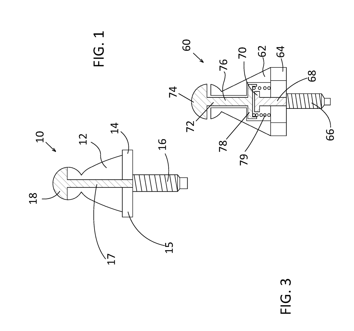
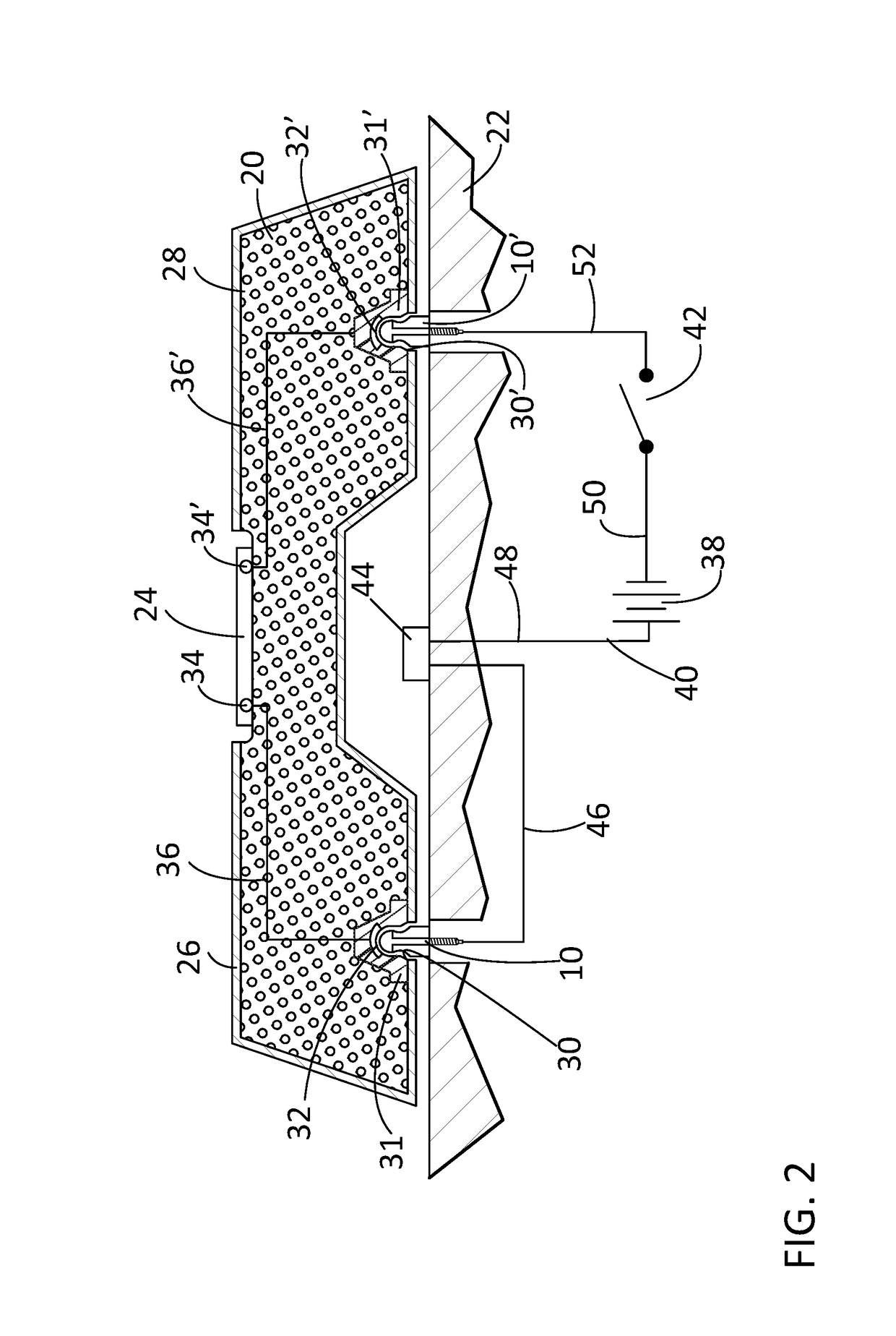
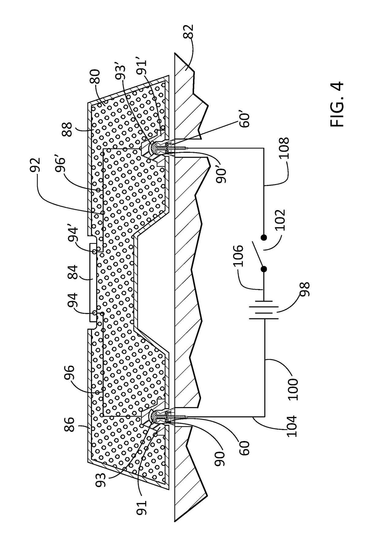
[0019]The accompanying figures and the associated description illustrate embodiments of a conductive ball stud fastener for use with a removably attachable electrified component. The component may be any of a broad variety of electrified components for attachment to and removal from a substrate that is also a power supply. It is to be understood that the shape and size of the ball stud fasteners and the associated electrified component as illustrated in the figures are suggestive and are not intended as being limiting. As a non-limiting example, the illustrated shape of the ball stud may instead be elongated or squared and may be adapted in any of several w...


PUM


Abstract

A conductive ball stud fastener arrangement for providing energy to a removable electrified component having an electrified element when the component is attached to an electrified substrate is disclosed. The ball stud fastener includes an insulating body, an electrified conductor having a conductive tip that is continuous with a conductive, centrally formed conductive stem, and a conductive attachment portion for attachment to the electrified substrate. The electrified component includes grommets having conductive elements. The ball stud fasteners are easily removed from and attached to the grommets. The conductive elements of the grommets are part of a circuit to which the electrified element of the electrified component is attached. According to one embodiment, the conductive ball stud fastener arrangement and its associated circuit includes a photoelectric sensor that opens and closes the circuit. In another embodiment, the ball studs themselves act as switches to open and close the circuit.

Description

TECHNICAL FIELD[0001]The disclosed inventive concept relates generally to conductive mechanical connectors for releasable attachment of components. More particularly, the disclosed inventive concept relates to a conductive ball stud strategy for use with hand-replaceable components that require electric power for operation. Two embodiments of the ball stud strategy of the disclosed inventive concept are set forth. One embodiment of the disclosed inventive concept incorporates a conductive ball stud having a conductive tip associated with an electric circuit having a photoelectric switch that de-energizes the circuit if the component is removed. Another embodiment of the disclosed inventive concept incorporates a conductive ball stud having a built-in safety switch and an associated electric circuit that is de-energized when the safety switch is moved to its open position.BACKGROUND OF THE INVENTION[0002]A number of components attached to an automotive vehicle require an electric cir...

Claims


Application Information

Patent Timeline
Patent Type & Authority Patents(United States)
IPC IPC(8): F02B77/02F02B63/02H01T13/06F02D41/30F02B77/11H01T13/18F02F7/00F16C11/06
CPCH01T13/18F02B63/02F02B77/11H01T13/06F02D41/3005F16C2326/01F02F2007/0041F16C11/06H01R12/7088H01R13/20H01R13/2421
Inventor NOLA, GARY
Owner FORD GLOBAL TECH LLC
Why Eureka
Try Eureka