Method and system for controlling a lighting network

a lighting network and lighting technology, applied in the integration of power network operation systems, sustainable buildings, instruments, etc., can solve the problems of affecting the safety of users, so as to achieve the effect of sacrificing the safety of users

Inactive Publication Date: 2019-02-19
AALTO UNIV FOUND
View PDF15 Cites 2 Cited by
  • Summary
  • Abstract
  • Description
  • Claims
  • Application Information

AI Technical Summary

Benefits of technology

[0011]An object of the invention is to alleviate and eliminate the problems relating to the known prior art. Especially the object of the invention is to provide a system for controlling, especially balancing consumption peaks in an electric power grid by controlling the usage or electric consumption of the lighting network without sacrificing the safety of the users, such as road users. In addition the object of the invention is to control the a lighting network based on a traffic monitoring so that any annoying flashing effect of the light sources in the network can be avoided.
[0015]In addition for controlling the lighting network also information related to a presence of users in said coverage areas is received, whereupon a status of at least certain luminaire is changed to a reserve status, when a last detected user exits the coverage area of said luminaire. The information related to a presence of users in certain areas can be obtained for example presence sensors determining motions or presence of users, such as from detecting sensors of traffic monitoring systems, position signals received from vehicles, such as vehicle positioning systems or position signals from smart phone applications. The presence information of users (either outdoor or indoor) in coverage areas may also comprise information of a type of said user, such as pedestrian, cyclist or vehicle, whereupon the maximum dimming level and / or the size of the coverage area may be determined based on the type of the user at least partly. For example pedestrians and bikes require a shorter length of lit road or other area than a car, whereupon the type of the user may also be taken into account when determining the size of the coverage area, and thereby saving significantly energy.
[0033]The present invention offers advantages over the known prior art, such as balancing effectively any consumption peaks in an electric power grid and avoiding the creation of short term spikes to the grid by controlling the usage or electric consumption of the lighting network. In addition, thanks to the invention, this can be done without sacrificing the safety of the users. Moreover disturbances to urban environments due to continuous switching on and off, or dimming and brightening of the lighting network, as well as any annoying flashing effect of the light sources in the network, can be avoided or at least minimized by the embodiment of the invention described in this document.
[0034]In addition the approach of the present invention is based on principles, where traffic safety is not degraded: each user may be detected individually and a level of lighting required by traffic safety regulations is provided to that user by real-time detection of the user and real time control of the luminaires to illuminate a sufficient length of in front of that user. In addition the smart street lighting system according to the invention is advantageously decoupled from the traffic monitoring system and is able to receive the traffic detection measurements over an Internet interface.

Problems solved by technology

There are however some disadvantages relating to the known prior art, such as the controlling is very often limited to quite narrow area, the switching of the certain portion of the lighting network induced consumption peaks into the electric power grid, as well as continuous switching on and off or even dimming and brightening easily disturbs urban environments.
Thus, any dimming done by the prior art solutions degrades traffic safety.
Moreover in the systems using motion detection the cost of installing and maintaining the dedicated motion detection electronics is very significant, and having such dedicated equipment implies that each system in a smart city that needs traffic monitoring data will have to have its own sensors.

Method used


Image

  • Method and system for controlling a lighting network
  • Method and system for controlling a lighting network
  • Method and system for controlling a lighting network

Examples


Embodiment Construction

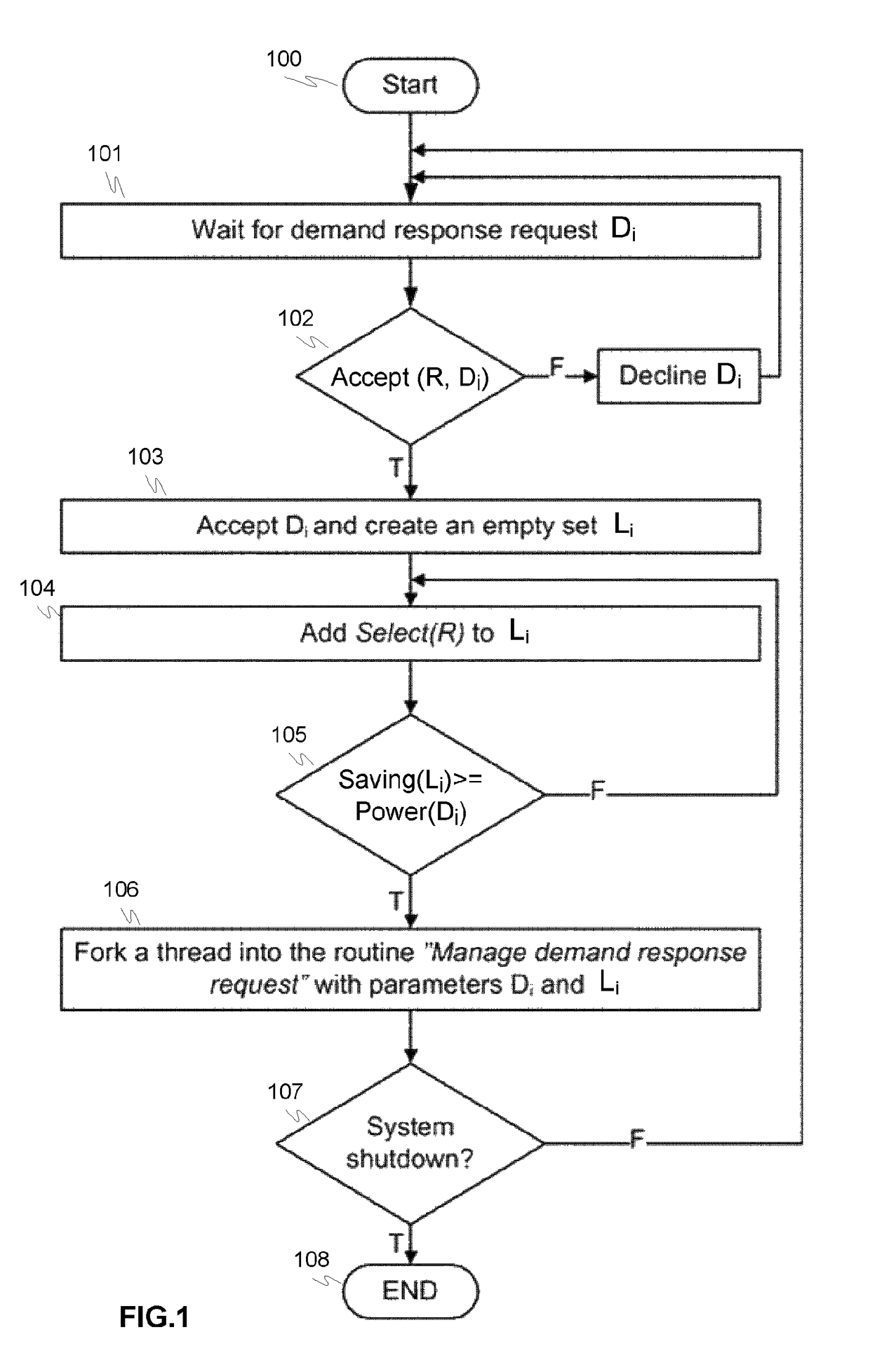
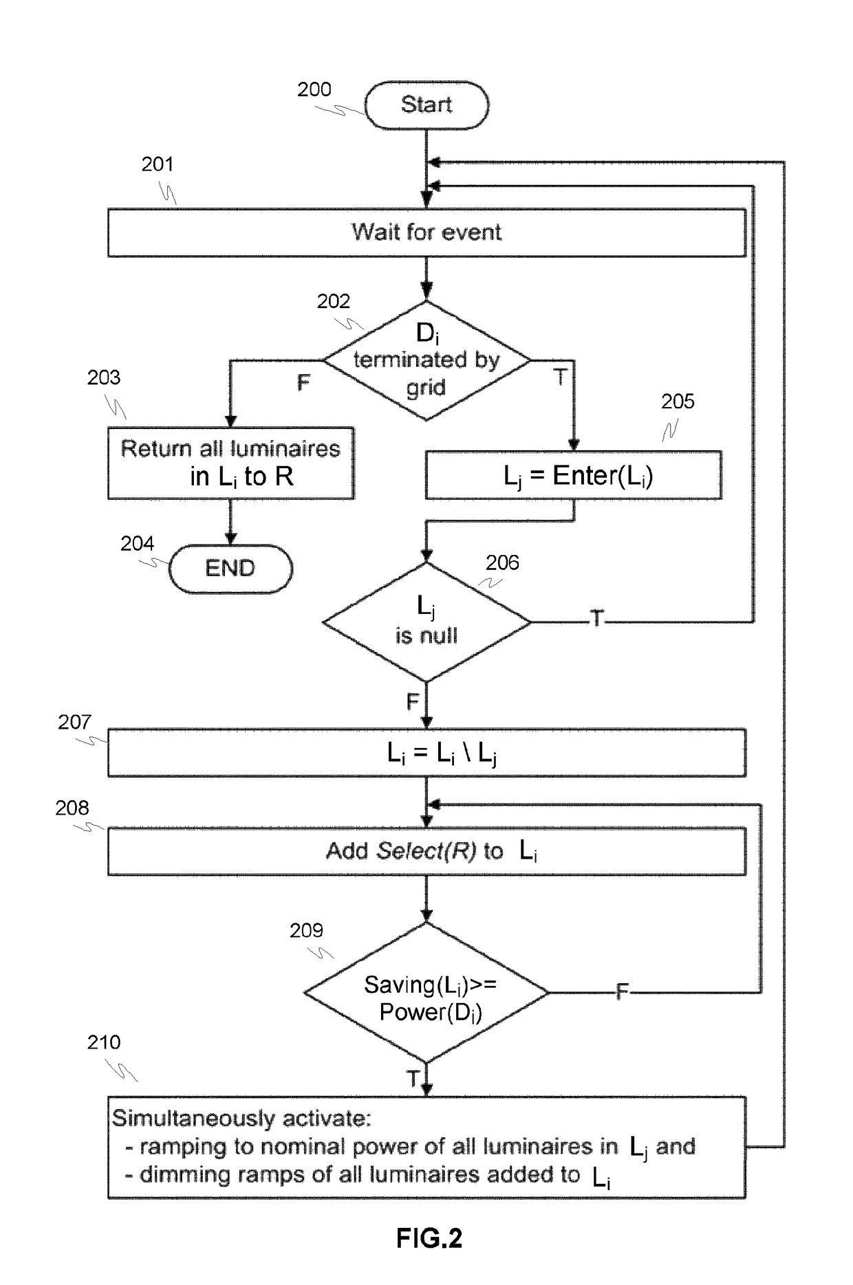
[0038]FIGS. 1-2 illustrate a principle of an exemplary method 100, 200 for controlling a lighting network based on traffic monitoring according to an advantageous embodiment of the invention, where in FIG. 1 a main routine 100 and in FIG. 2 manage demand response request routine are described in more details.

[0039]The method exploits the capability of individual LED luminaires to be adjusted frequently and rapidly without adverse impacts on the lifetime of the luminaire. In the method the presence of road users is detected and much more significant dimming is performed when there are no road users in the coverage range of the luminaire. There are several possibilities for performing the detection, including but not limited to: (1) traffic monitoring systems using sensors to detect road users, (2) position signals from vehicles or (3) smart phone applications. When the last road user exits the coverage range of the luminaire, no dimming action is necessarily performed, but the street...


PUM


Abstract

A controlling of a lighting network based on traffic monitoring comprises steps of determining plurality of coverage areas of set of luminaires, where each luminaire comprises at least one light source. Information related to a presence of users in said coverage areas is received. This may relate both outdoor or indoor areas and activity. A status of at least certain luminaire is then changed to a reserve status, when a last detected user exits the coverage area. Each coverage area or luminaire is providing with an expected value for the time of when the next user is expected to arrive in the coverage area of said luminaire, A set of luminaires [R] of said luminaires with the reserve status to be controlled, such as dimmed, is then defined and information related to demand response requests [D1, . . . , Dn] of an electric power grid is received. In addition controlling, such as dimming, at least one of said defined set of luminaires in said reserve is performed in order to fulfill said demand response requests at least partially.

Description

PRIORITY[0001]This application is a U.S national application of PCT-application PCT / FI2015 / 050716 filed on Oct. 21, 2015 and claiming priority of Finnish national application FI20145923 filed on Oct. 21, 2014, the contents of all of which are incorporated herein by reference.TECHNICAL FIELD OF THE INVENTION[0002]The invention relates to a method and system for controlling a lighting network based on a traffic monitoring, wherein the lighting network comprises set of luminaires, and each luminaire comprises at least one light source.BACKGROUND OF THE INVENTION[0003]Numerous of systems for controlling a lighting network based on a traffic monitoring are known, where the individual light sources or group consisting of plurality of light sources are switched off or switched on. The switching is often done by using some light sensors or timer, when controlling lighting network due to environmental parameters (light condition), or motion sensor or other suitable devices when the controlli...

Claims


Application Information

Patent Timeline
Patent Type & Authority Patents(United States)
IPC IPC(8): H05B37/02H05B33/08H05B37/03G06K9/00H05B44/00
CPCH05B37/0245G06K9/00785H05B33/0845H05B37/0272H05B37/034H05B37/0227Y02B20/72H05B47/175H05B47/19H05B45/10H05B47/115Y02B70/30Y02B70/3225Y04S20/246Y04S20/222H05B47/105H02J3/14H05B47/22G06V20/54
Inventor SIERLA, SEPPO
Owner AALTO UNIV FOUND
Why Eureka
Try Eureka