
Power transmission device

a technology of power transmission and transmission device, which is applied in the direction of positive displacement liquid engine, piston pump, gearing, etc., can solve the problems of reducing allowance, affecting the design of breakable parts, and affecting the operation of power transmission

Inactive Publication Date: 2006-05-09
DENSO CORP
View PDF8 Cites 3 Cited by
  • Summary
  • Abstract
  • Description
  • Claims
  • Application Information

AI Technical Summary

Benefits of technology

[0013]With this construction, the fatigue limit of the breakable part 13d is made lower than it normally is after the torque has exceeded the predetermined torque level. Therefore, the breakable part 13d will reliably break before the torque reaches the upper limit of the operation range. The present invention thus provides a power transmission device with a novel construction that can interrupt power transmission precisely at a preset torque limit without sacrificing safety during normal use, i.e., without inducing the risk of fatigue fracture of the breakable part 13d.
[0017]The present invention thus provides a power transmission device with a novel construction that can interrupt power transmission precisely at a preset torque limit without limiting safety requirements during normal use, i.e., without inducing the risk of fatigue fracture of the breakable part 13d.

Problems solved by technology

The groove breaks when the applied torque exceeds a predetermined torque level, thereby interrupting power transmission.
On the other hand, it involves difficulties in designing the breakable part for the following reasons.
However, this will greatly reduce the allowance between the peak torque during normal use and the fatigue limit of the breakable part, thus increasing the risk that the breakable part will break due to fatigue during normal use.

Method used


Image

  • Power transmission device
  • Power transmission device
  • Power transmission device

Examples


first embodiment

(First Embodiment)

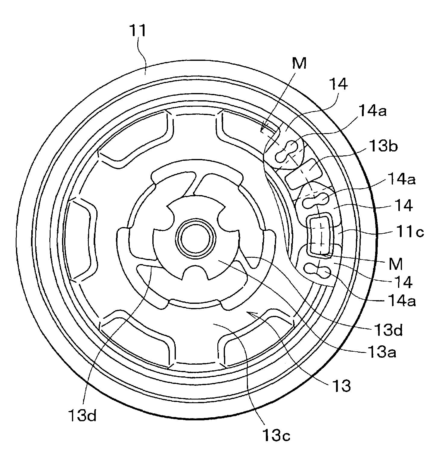
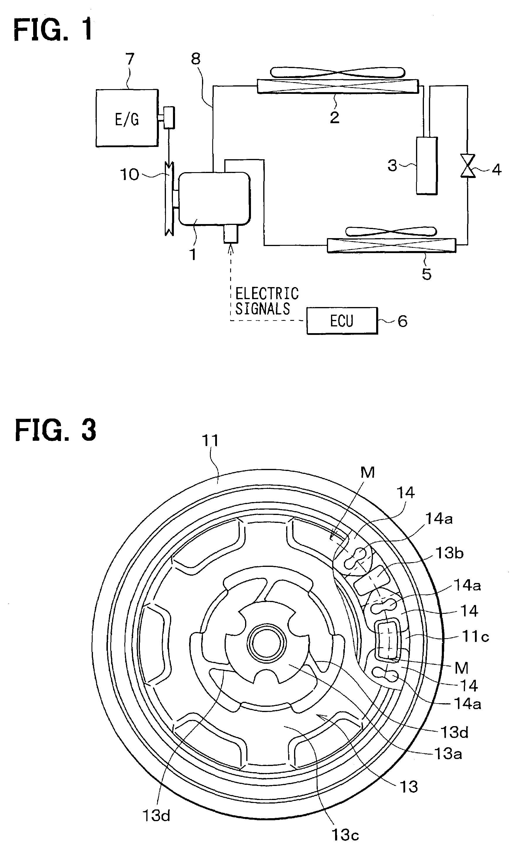
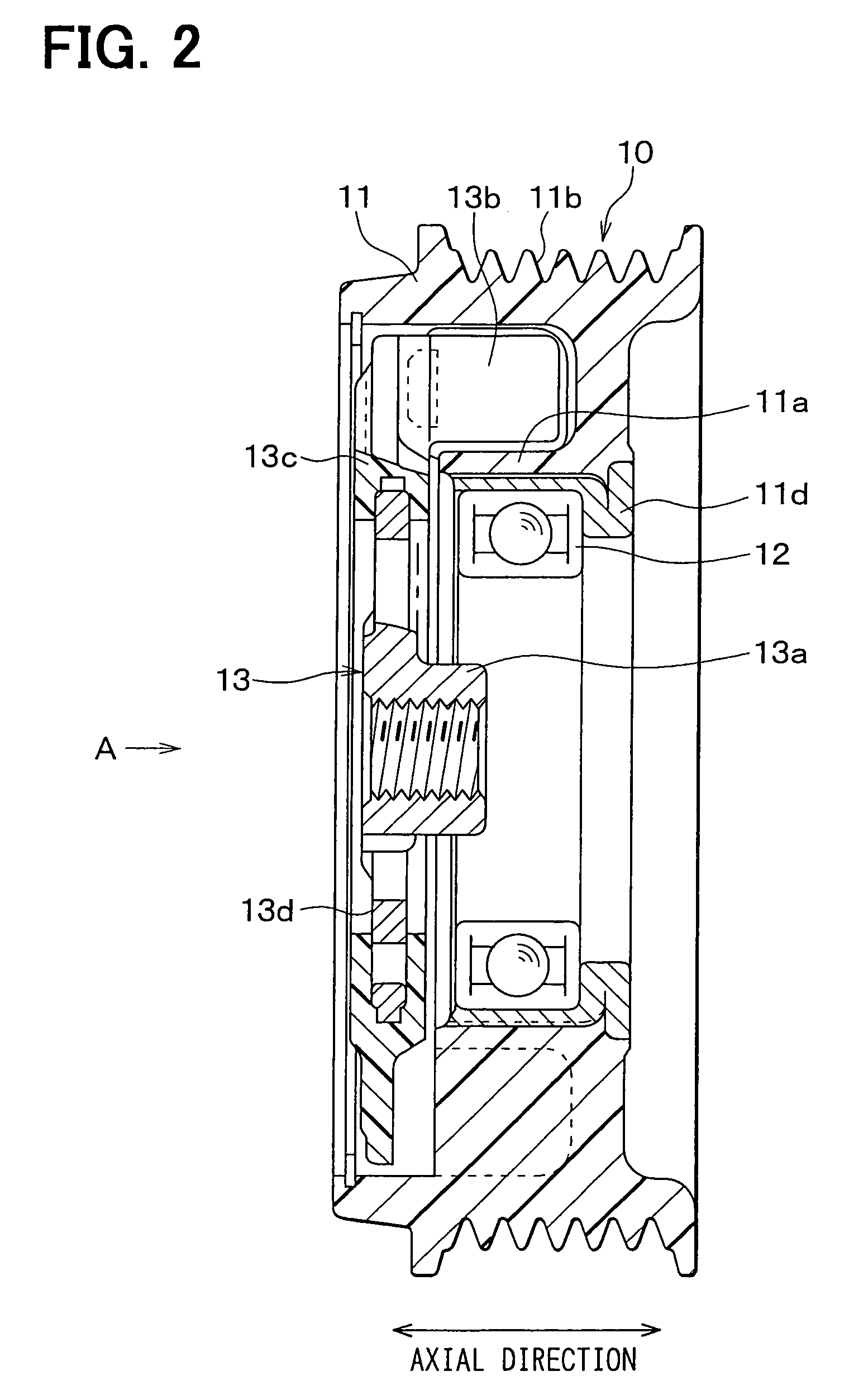
[0036]The power transmission device according to the present invention is embodied as a pulley 10 that transmits power to a compressor 1 of a vehicle air conditioning system. FIG. 1 is a model diagram of the vehicle air conditioning system which comprises a vapor compression refrigerator, FIG. 2 is a cross-sectional view of the pulley 10, FIG. 3 is a view taken from the direction of arrow A of FIG. 2, and FIG. 4 is a cross-sectional taken along the line M—M of FIG. 3.

[0037]The vapor compression refrigerator is made up of a condenser 2 that removes heat from the high temperature, high pressure refrigerant compressed by the compressor 1 by exchanging heat with outside air to cool the refrigerant, a receiver 3 for collecting liquefied refrigerant flowing from the condenser 2 after gaseous refrigerant has been separated therefrom, an expansion valve 4 for depressurizing the liquid refrigerant supplied from the receiver 3, and an evaporator 5 for evaporating the low tem...

second embodiment

(Second Embodiment)

[0053]In the previous embodiment, the slanted faces 15 are formed on the main body 11 of the pulley, on which the projections 13b of the center hub 13 abut to move the center hub 13 in the axial direction. FIG. 8A and FIG. 8B show another embodiment in which slanted faces 15 are formed on the dampers 14. The center hub 13 is also formed with slanted faces 13f that are substantially parallel to the slanted faces 15. These make contact with each other when the torque exceeds the predetermined torque level and causes the center hub 13 to move in the axial direction.

(Other Embodiments)

[0054]Various other changes and modifications may be made to the above described embodiments. For example, the slanted faces should not be limited to flat surfaces but may be formed as curved surfaces 16 as shown in FIG. 9. Also, instead of being a simple bar-like form, bridges 13d may be formed with notches 13e as shown in FIG. 10 so that bending stress will be concentrated therein.

[005...


PUM


Abstract

A power transmission device which interrupts torque transmission when the torque exceeds a predetermined torque. A torque limiter includes projections formed on a center hub and a pulley. The center hub includes bridges that transmit torque by a pulling force. When a preset torque limit is reached, the projections on the center hub make contact with and move along slanted faces so as to move the center hub in an axial direction relative to the pulley. The bridges are thereby subjected to a bending moment in addition to the pulling force when the torque exceeds the preset torque level, so that the bridges break precisely above the preset torque level due to the reduced fatigue limit.

Description

CROSS REFERENCE TO RELATED APPLICATION[0001]This application is based upon, claims the benefit of priority of, and incorporates by reference, the contents of Japanese Patent Application No. 2002-155160 filed May 29, 2002.BACKGROUND OF THE INVENTION[0002]1. Field of the Invention[0003]The present invention relates to a power transmission device such as a pulley or electromagnetic clutch suitably used for driving a compressor for an air conditioning system, and more particularly to its torque limiting mechanism that interrupts torque transmission when the torque exceeds a predetermined torque level.[0004]2. Description of the Related Art[0005]Torque limiting mechanisms provide overload protection to drive source components such as belts by interrupting torque transmission when the driven side (i.e. driving) equipment is inhibited from rotating by a failure such as seizure of the sliding and rotating parts of a compressor.[0006]One prior art example of a power transmission device havin...

Claims


Application Information

Patent Timeline
Patent Type & Authority Patents(United States)
IPC IPC(8): F16D9/04F16D9/00F16D9/06F16H35/10
CPCF16D9/06Y10T477/621F16H2035/103
Inventor NOSAKA, MICHIYASUKUROHATA, KIYOSHI
Owner DENSO CORP
Learn More