Ultrasound head frame for emergency medical services

a head frame and ultrasonic technology, applied in the field of head frames, can solve the problems of unfavorable maintenance of such head frames, and achieve the effects of wasting valuable time (and brain) and being easy to apply to patients, improving stroke treatment outcomes, and saving valuable tim

Inactive Publication Date: 2019-02-26
KONINKLJIJKE PHILIPS NV
View PDF14 Cites 2 Cited by
  • Summary
  • Abstract
  • Description
  • Claims
  • Application Information

AI Technical Summary

Benefits of technology

[0013]Also, the “blind therapy” approach of providing multiple therapy beams with the intention of one or more being aimed at the blood clot has the unintended side effect that healthy brain tissue is treated unnecessarily.
[0014]An STL head frame, according to embodiments of what is proposed below, is designed specifically to meet the requirements for holding the probes against a patients' head for robust probe placement, for quick application by EMS personnel and for providing STL therapy during patient transport to the treatment center, compatible with current EMS workflow.
[0016]Such coupling and alignment should be robust, stable, resist vibrations, resist patient / probe relative motion, be comfortable, and easily applied to the patient. It should allow for probe coupling for the entire duration of the STL treatment, even during patient transport. Stroke treatment outcomes are generally better the earlier a patient is treated for the stroke (“time is brain”). Thus treatment at the point-of-care site and during transport is highly desirable. Currently, stroke patients are not treated for stroke until after arrival at a hospital and / or stroke unit, wasting valuable time (and brain).

Problems solved by technology

While comfortable, it is unlikely that such head frames would withstand the rigors of maintaining accurate probe alignment and targeting to the clot in an emergency vehicle, where the patient and his / her head is constantly in motion because of the motion of the emergency vehicle itself.

Method used


Image

  • Ultrasound head frame for emergency medical services
  • Ultrasound head frame for emergency medical services
  • Ultrasound head frame for emergency medical services

Examples


Embodiment Construction

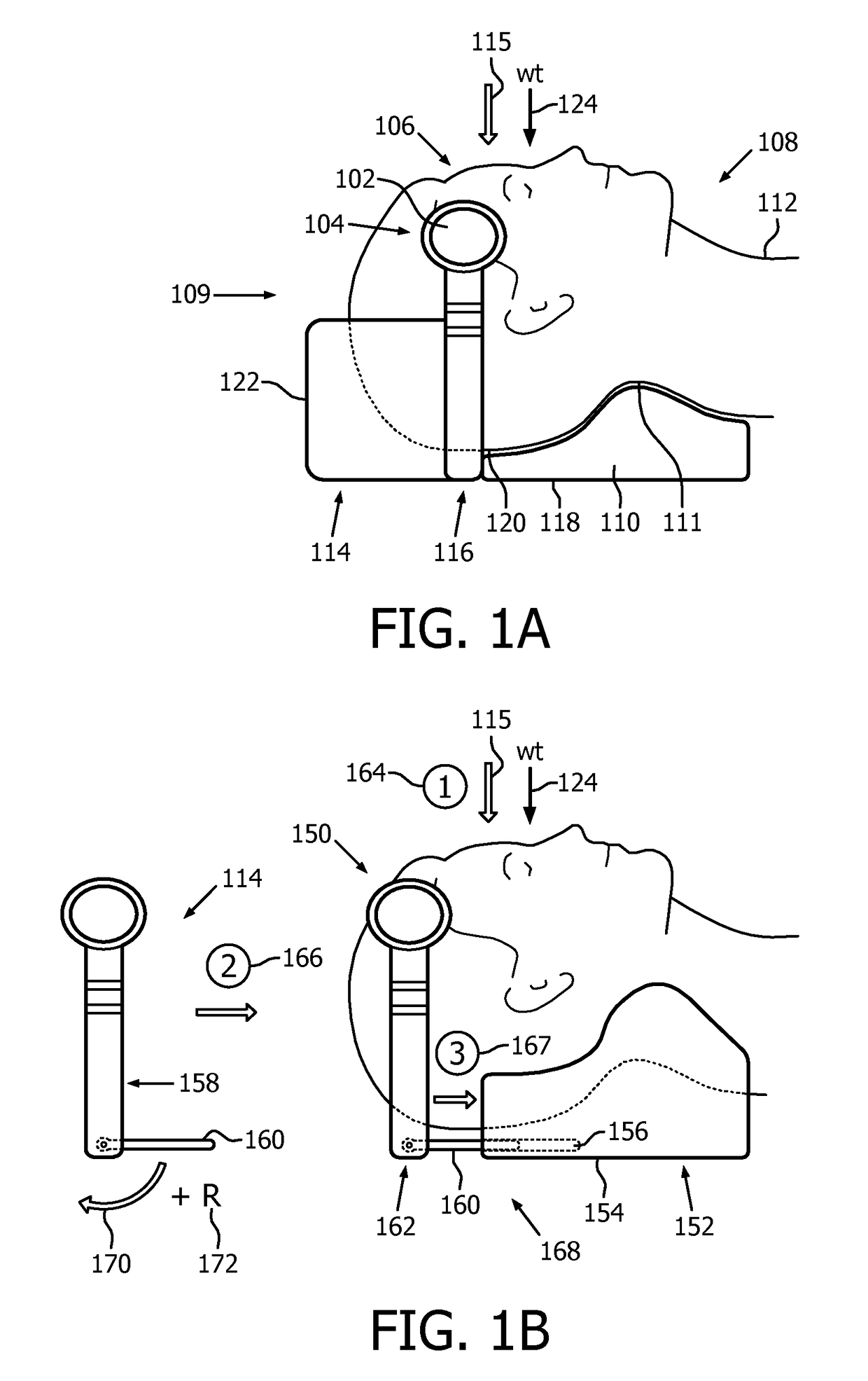
[0026]FIG. 1A depicts, by way of illustrative and non-limitative example, an integrated head frame 100. It has a circular opening 102 for holding an imaging probe (or a therapy probe, or a combined imaging / therapy probe, not shown) such as one used for ultrasound imaging. The distal tip of the probe is placed against a temple, or temporal bone region, 104 of a head 106 of a medical patient 108. Located within the temporal bone region 104 is the acoustic window in the skull with minimum acoustic attenuation. The head frame 100 is specifically designed for use for an EMS patient 108 in the supine position 109, i.e., lying down facing upward. Although basic components of the head frame 100 may be integrated or not normally separable, parts of the head frame may be made detachable for cleaning or replacement.

[0027]The head frame 100 includes a neck support 110 conformal with the back 111 of the neck 112, and has a configuration 113 that wraps around the head 106.

[0028]In particular, the...


PUM


Abstract

A head frame for a medical patient includes support for a probe and a neck support. The frame wraps around the head of the patient and can be used in the supine position. The support may include a probe holder slidable under the head and configured to contact or engage the neck support. In some embodiments, conformal shaping to the head and / or neck of the patient, the frame's rigid construction, the alignment of the optionally separable holder to the neck support, the weight of the head, or a combination thereof serve to keep the distal tip of the ultrasound probe in place against the temporal region of the head without need for attaching the frame to the head as by straps, which may provide an arrangement robust against patient / vehicle movement in an emergency medical services setting.

Description

CROSS-REFERENCE TO PRIOR APPLICATIONS[0001]This application is the U.S. National Phase application under 35 U.S.C. § 371 of International Application No. PCT / IB2013 / 059268, filed on Oct. 10, 2013, which claims the benefit of U.S. Provisional Patent Application No. 61 / 716,007, filed on Oct. 19, 2012 and U.S. Provisional Patent Application No. 61 / 865,279, filed on Aug. 13, 2013. These applications are hereby incorporated by reference herein.FIELD OF THE INVENTION[0002]The present invention relates to a head frame for supporting a probe for imaging, therapy or both and, more particularly, to a head frame that includes neck support and wraps around the head.BACKGROUND OF THE INVENTION[0003]Sonothrombolysis (STL) is an emerging non-invasive stroke treatment modality in which ultrasound and microbubbles are used to lyse the clot causing the occlusion in acute ischemic strokes. In these treatments, ultrasound (used to both image / locate the occlusion in the brain vasculature and treat it), ...

Claims


Application Information

Patent Timeline
Patent Type & Authority Patents(United States)
IPC IPC(8): A61B8/00A61B8/08A61G1/04A61N7/00A61B8/06A61B90/14
CPCA61B8/4209A61B8/40A61B8/429A61B8/4427A61G1/04A61N7/00A61B8/0808A61N2007/0052A61B8/06A61B8/0816A61B8/4411A61B8/4455A61B90/14A61N2007/0021A61N2007/0026A61N2007/0039
Inventor RINCKER, MAARTEN JOHAN FRIDOKELLY, JULIANA PAULINESEIP, RALFPOWERS, JEFFRY EARLSHI, WILLIAM TAOULLERUP, HELLESCHAEKEN, DAVY MARIA WILLIBRORDUSSWEENEY, TERRENCE JAMES
Owner KONINKLJIJKE PHILIPS NV
Why Eureka
Try Eureka