Golf shaft

a golf club and shaft technology, applied in the field of golf clubs, can solve the problems of low performance low development speed of the putter shaft, so as to achieve the effect of improving stability and enhancing performance characteristics

Active Publication Date: 2019-02-26
BREAKTHROUGH GOLF TECH LLC
View PDF88 Cites 3 Cited by
  • Summary
  • Abstract
  • Description
  • Claims
  • Application Information

AI Technical Summary

Benefits of technology

[0007]A golf shaft having a butt portion joined to a tip portion by a coupler and possessing unique relationships, including rigidity relationships, which provide beneficial performance characteristics including improved stability.

Problems solved by technology

During the course of a golf swing, the club shaft is under a load and is subject to often significant deflection and torsional rotation.
While driver, fairway metal, and hybrid shafts have evolved over the past 30 plus years, from steel tubes to a variety of often complex composite shafts, putter shafts have not evolved at pace.
No serious golfer trusts their driver to perform optimally with an inexpensive steel shaft.
They are narrow in the tip and taper to a larger diameter at the butt-end for gripping purposes, and consequently exhibit inherent weakness in the lower portion of the shaft.
Ultimately, the impetus for steel shafts continued preeminence is cost: steel shafts are used by putter manufacturers primarily because they are so cheap.

Method used


Image

  • Golf shaft
  • Golf shaft
  • Golf shaft

Examples


Embodiment Construction

[0030]The description set forth below in connection with the drawings is intended merely as a description of the presently preferred embodiments of the invention, and is not intended to represent the only form in which the present invention may be constructed or utilized. The description sets forth the designs, functions, means, and methods of implementing the invention in connection with the illustrated embodiments. It is to be understood, however, that the same or equivalent functions and features may be accomplished by different embodiments that are also intended to be encompassed within the spirit and scope of the invention.

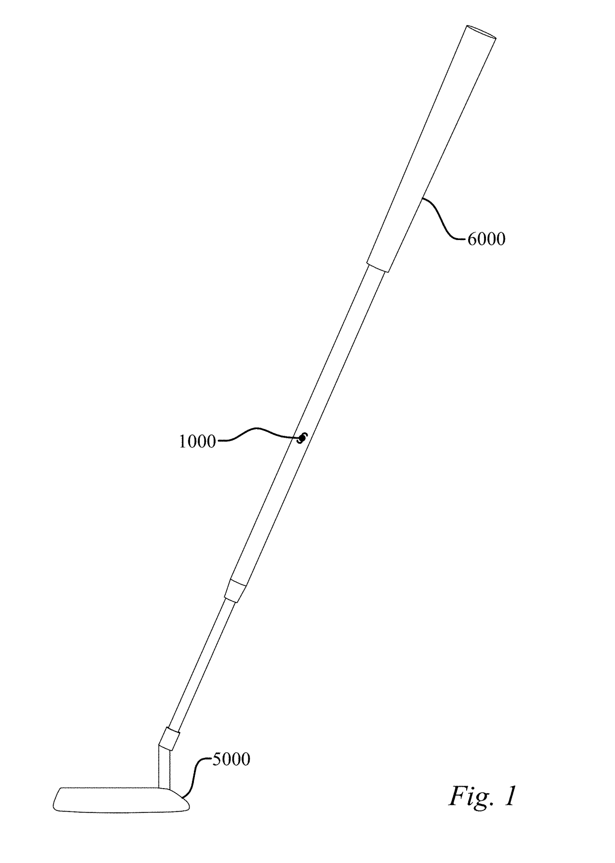
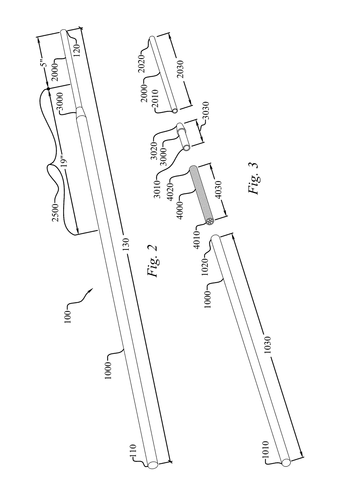
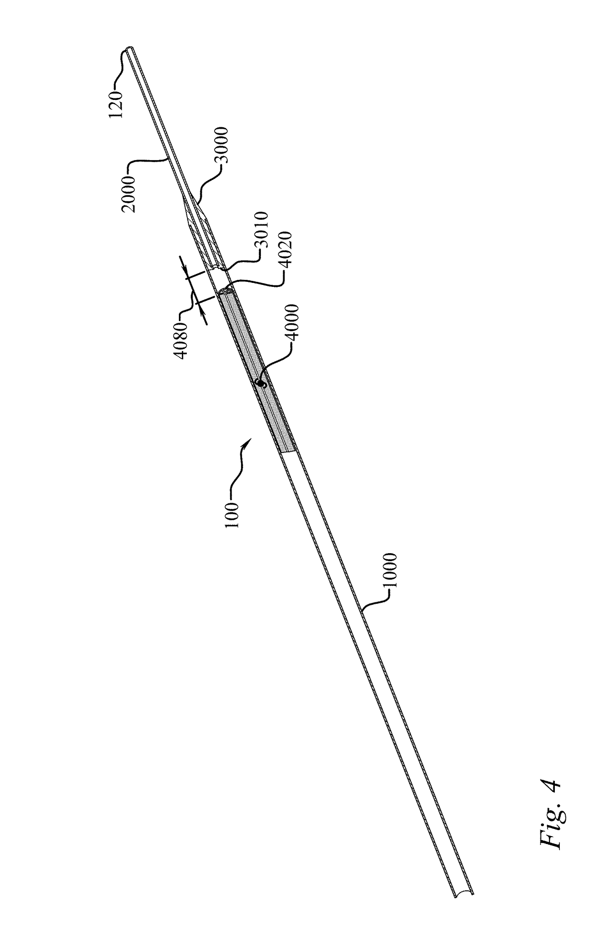
[0031]As seen in FIGS. 1-8, an embodiment of the shaft (100) of the present invention includes a shaft distal end (110), a shaft proximal end (120), a shaft outer diameter, and a shaft mass, wherein each point along the shaft length (130) has a shaft flexural rigidity, often abbreviated EI, and a shaft torsional rigidity, often abbreviated GJ. The shaft (100)...


PUM


Abstract

A golf shaft having a butt portion joined to a tip portion by a coupler and possessing unique relationships, including rigidity relationships, which provide beneficial performance characteristics including improved stability.

Description

CROSS-REFERENCE TO RELATED APPLICATIONS[0001]Not Applicable.STATEMENT REGARDING FEDERALLY SPONSORED RESEARCH OR DEVELOPMENT[0002]This invention was not made as part of a federally sponsored research or development project.TECHNICAL FIELD[0003]The present invention relates to sports equipment; particularly, to a golf club shaft.BACKGROUND OF THE INVENTION[0004]During the course of a golf swing, the club shaft is under a load and is subject to often significant deflection and torsional rotation. Few have recognized that this deflection and rotation, albeit on a much smaller scale, also happens during the course of a putting stroke, particularly as the head weight of putter heads increases. As used herein, “stability” of a shaft refers to how the toe and heel of the club face track one another through the stroke. The relative volatility of the velocity and acceleration of the toe and heel of the club face pre-impact, at impact, and post-impact can be significantly improved. Controlling...

Claims


Application Information

Patent Timeline
Patent Type & Authority Patents(United States)
IPC IPC(8): A63B53/10A63B53/12A63B53/00
CPCA63B53/10A63B53/12A63B53/007A63B60/08A63B60/26
Inventor ADAMS, BYRON H.PHILIP, BLAIR M.HALSTEAD, JEFFREY T.STEPHENS, ROBERT E.NAPIER, TREVER M.MACKAY, JAMES P.
Owner BREAKTHROUGH GOLF TECH LLC
Why Eureka
Try Eureka