
Systems and methods for providing prosthetic components

a technology of prosthetic components and components, applied in the field of prosthetics, can solve the problems of inability of knee prosthesis patients to achieve deep knee flexion, also known as full functional flexion, and not allow patients to flex from full extension to 160° and beyond, so as to achieve and greater deep knee flexion

Inactive Publication Date: 2019-02-26
SAMUELSON CONNOR E +3
View PDF116 Cites 1 Cited by
  • Summary
  • Abstract
  • Description
  • Claims
  • Application Information

AI Technical Summary

Benefits of technology

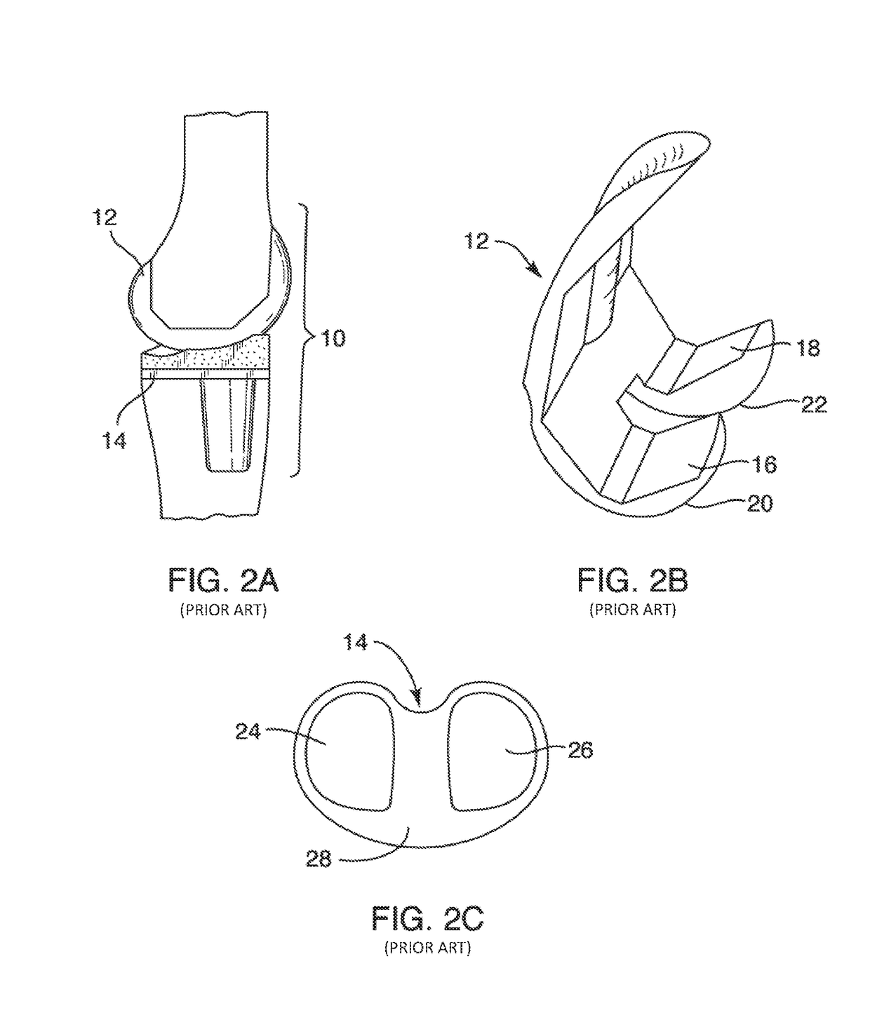
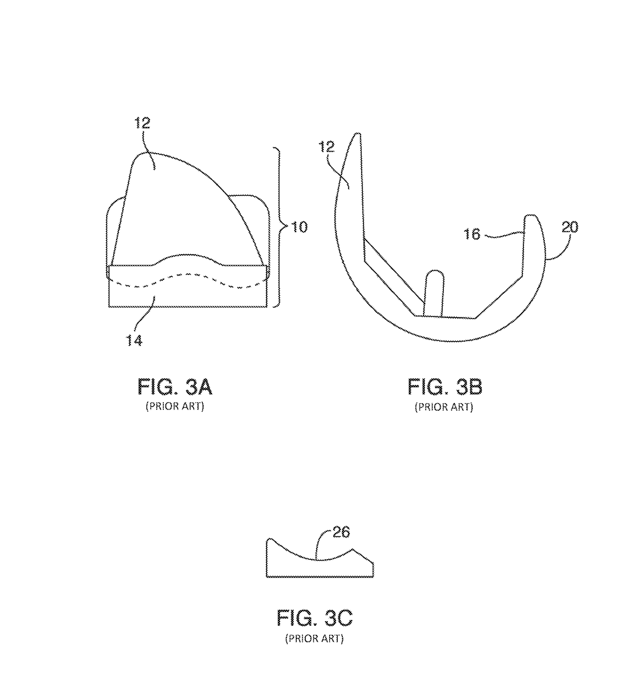
The present invention provides systems and methods for improving knee prostheses to allow patients to achieve greater deep knee flexion. This is achieved by resecting portions of the femur and replacing them with a femoral component that does not have an anterior flange as seen on contemporary prostheses. Other methods include providing a greater articular surface area to the femoral component, adding an asymmetrical under surface on the tibial component, and replacing a portion of the femoral acondyles with an asymmetrical articular surface. The invention also relates to improvements in customization of prosthetics and the positioning of articular surfaces in resected portions of the femur. Overall, the invention enhances knee prostheses to provide greater deep knee flexion and improved outcomes for patients.

Problems solved by technology

Unfortunately, some of today's knee prostheses still have shortcomings.
Among these shortcomings is the inability of a knee prosthesis patient to achieve deep knee flexion, also known as full functional flexion.
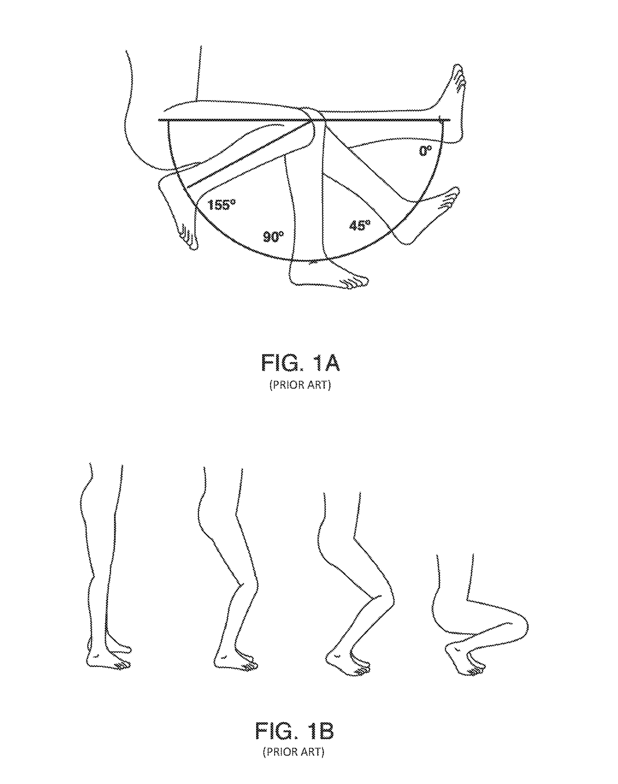
Though some currently available knee prostheses allow for knee flexion (i.e., bending) of more than 130° from full limb extension (0° being when the patient's knee is fully extended and straight); some such prostheses do not allow patients to flex from full extension to 160° and beyond (e.g., to full functional and / or deep knee flexion).
Most conventional knee prosthesis patients are unable to consistently achieve the latter position or any position placing the knee joint at angles above 130° (e.g., at 160° and beyond).
For many people, such a limb and body position is not often achieved or desired most of the time.
Unfortunately, those with currently-available knee prostheses are unable to participate in any activity requiring greater knee flexion and are thus limited to watching from the sidelines.
For instance, in some Asian and Indian cultures, full functional flexion and the squatting position is common and performed for relatively long periods of time.
In this regard, as such a bone may experience less of the flexion forces than would typically strengthen the bone, such a bone may actually become weak and resorb.
Additionally, in some cases as the bone surrounding a rigid shaft flexes, micro-abrasions may occur at the interface between the bone and the stem, resulting in the loss of bone at the interface.
As a result, some such prostheses may do little to prevent fractures from forming and spreading in the femur (e.g., at stress risers created as a consequence of bone cuts that were made to allow the femoral prosthesis to be seated on the femur).
As yet another example, although some femoral prostheses comprise a stem to strengthen the femur's distal end, such stems often place significant limits on the physical characteristics of the femoral prosthesis that can be used therewith.
Additionally, in some cases in which a femoral prosthesis includes a stem, the stem can also limit the manner in which the femoral prosthesis can be attached to a femur.
Thus, while techniques currently exist that relate to prosthetic implants (such as knee prostheses), challenges with such implants still exist, including those discussed above.

Method used


Image

  • Systems and methods for providing prosthetic components
  • Systems and methods for providing prosthetic components
  • Systems and methods for providing prosthetic components

Examples


Embodiment Construction

[0118]Some aspects of the present invention relates to prosthetic implants. More specifically, while some aspects of the present invention relate to prosthetic knee implants that allow for a relatively high degree of knee flexion, other aspects relate to systems and methods for providing relatively lightweight prosthetic implants.

[0119]The following disclosure of the present invention is grouped into two subheadings, namely “High Flexion Knee Components” and “Lightweight Prosthetic Implants.” The utilization of subheadings is for convenience of the reader and is not, in any way, to be construed as limiting in any sense.

High Flexion Knee Components

[0120]With respect to the high flexion knee components, some aspects of the present invention relates to knee prostheses. In particular, some implementations of the present invention relate to systems and methods for providing deeper knee flexion capabilities for knee prosthesis patients, and more particularly, to systems and methods for: (...


PUM


Abstract

Methods for forming prosthetic implants, including femoral implants, are discussed. While the methods can include any suitable step, in some cases, they include providing a master negative mold defining an internal space shaped to form a femoral component configured to replace a distal portion of a femur, wherein the femoral component comprises at least one of: an anterior flange that is disposed at an anterior proximal end of the femoral component, and a proximal extension disposed at a proximal portion of a posterior condyle of the femoral component, the proximal extension comprising a concave articulation surface that is configured to articulate against at least one of: a tibial prosthetic component and a tibia; filling the master negative mold with a molding material to form a molded femoral component; and removing at least one of: the anterior flange, and the proximal extension from the molded femoral component to form a modified molded femoral component. Other implementations are described.

Description

RELATED APPLICATIONS[0001]This is a continuation-in-part application of U.S. patent application Ser. No. 14 / 975,736, filed Dec. 19, 2015, and entitled SYSTEMS AND METHODS FOR PROVIDING A FEMORAL COMPONENT HAVING A MODULAR STEM, which is a continuation-in-part application of U.S. patent application Ser. No. 14 / 828,340, filed Aug. 17, 2015, and entitled SYSTEMS AND METHODS FOR PROVIDING A FEMORAL COMPONENT, which is a continuation application of U.S. patent application Ser. No. 13 / 802,596, filed Mar. 13, 2013, and entitled SYSTEMS AND METHODS FOR PROVIDING A FEMORAL COMPONENT, which is a continuation-in-part application of U.S. patent application Ser. No. 13 / 758,855 (now U.S. Pat. No. 9,101,478), filed Feb. 4, 2013, and entitled SYSTEMS AND METHODS FOR PROVIDING STEM ON A TIBIAL COMPONENT, which is a continuation application of U.S. patent application Ser. No. 12 / 797,372 (now U.S. Pat. No. 8,366,783), filed Jun. 9, 2010, and entitled SYSTEMS AND METHODS FOR PROVIDING DEEPER KNEE FLEXI...

Claims


Application Information

Patent Timeline
Patent Type & Authority Patents(United States)
IPC IPC(8): A61B17/17A61F2/38B22D23/00B22C9/22B22D25/02B22D23/02A61F2/30B22D25/00A61B17/15
CPCA61B17/1764B22C9/22A61F2/389A61F2/3859B22D23/00B22D23/02B22D25/02B22D25/00A61B17/155A61F2/30965A61F2/3877A61F2002/30018A61F2002/30029A61F2002/30116A61F2002/30245A61F2002/30604A61F2002/30934A61F2002/3863A61F2002/3895A61F2310/00011A61F2310/00179A61F2310/00329A61F2310/00353B22C9/10A61F2002/30014A61F2002/30028
Inventor SAMUELSON, CONNOR ESAMUELSON, MARCUS F.SAMUELSON, ALEC C.SAMUELSON, KENT M.
Owner SAMUELSON CONNOR E
Learn More