
Low power standby for a powered device in a power distribution system

a power distribution system and low power technology, applied in the field of low power standby of powered devices in power distribution systems, can solve the problems of energy waste, approximately a minimum of 100 mw of power consumption, and the powered device does not draw enough power for the power providing device, so as to save the need for adding an additional componen

Active Publication Date: 2019-02-26
SIGNIFY HLDG BV
View PDF19 Cites 3 Cited by
  • Summary
  • Abstract
  • Description
  • Claims
  • Application Information

AI Technical Summary

Benefits of technology

This approach reduces energy consumption during standby mode by ensuring the power providing device continues to supply power only when necessary, thereby enhancing electrical efficiency and preventing unnecessary energy wastage.

Problems solved by technology

Especially in a standby mode, energy is ‘wasted’ in many power distribution systems in order to create a keep-alive type signal.
Although the MPS needs only to be generated periodically, it leads to approximately a minimum of 100 mW of power consumption.
When in the standby mode, the powered device does not draw sufficient power for the power providing device to remain powering the powered device.
However, when small amounts of power are drawn, electrical components that are part of the powered can filter out the pulse, change its shape, etc., thereby preventing the power providing device from sensing the current flow and thereby preventing the power providing device from remaining to provide power to the powered device.

Method used


Image

  • Low power standby for a powered device in a power distribution system
  • Low power standby for a powered device in a power distribution system
  • Low power standby for a powered device in a power distribution system

Examples


Embodiment Construction

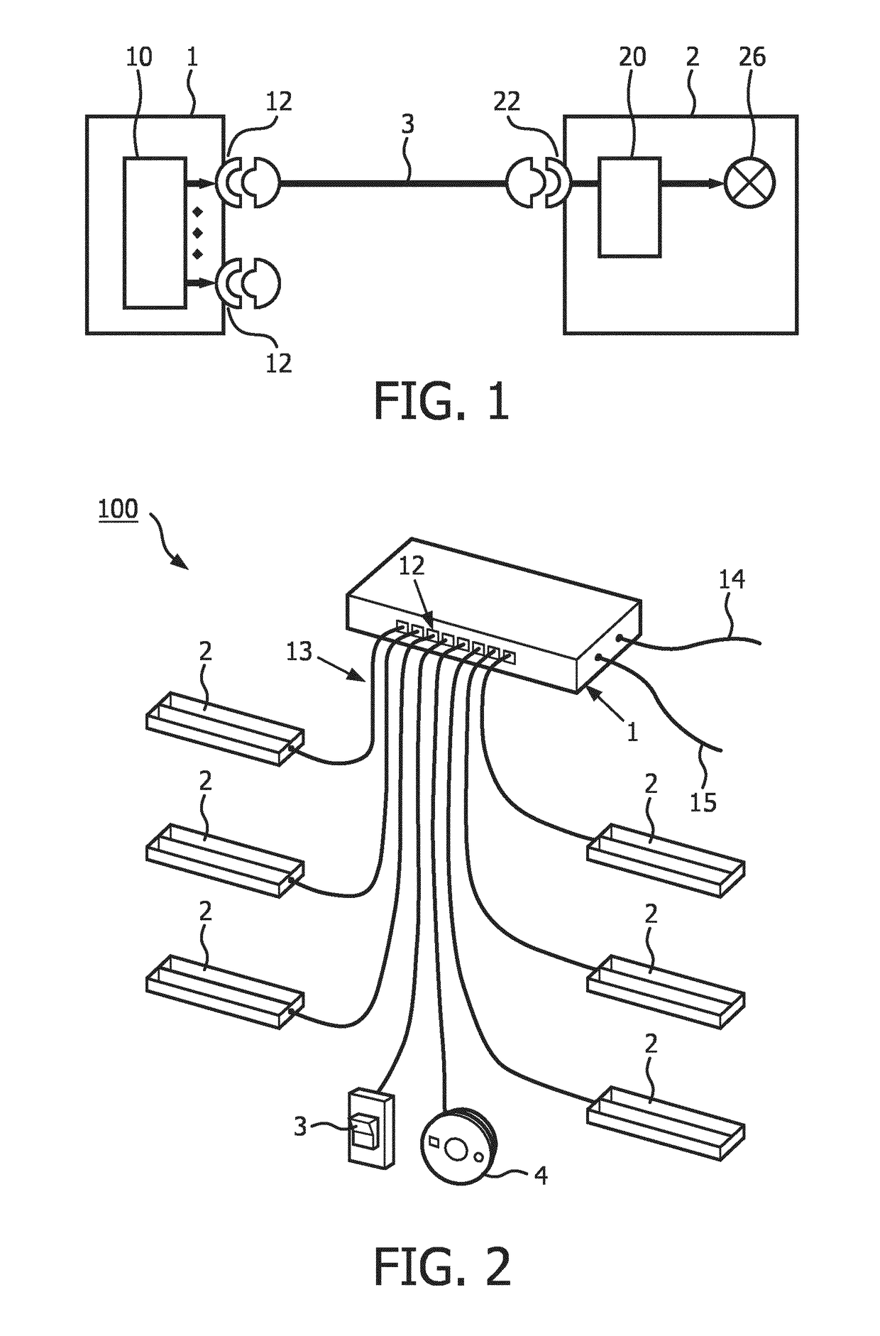
[0039]The IEEE 802.3af / at standards define a power and data distribution system, which allows distributing power and data via a twisted-pair Ethernet cable. According to this standard, electrical consumers can be connected to a switch for receiving power from the switch and for exchanging data, wherein the switch comprises several ports and wherein to each port a single electrical consumer can be connected. Ethernet is a family of computer networking technologies for local area networks (LANs). Ethernet was commercially introduced in 1980 and standardized in 1985 as IEEE 802.3 by the IEEE. Ethernet has largely replaced competing wired LAN technologies. The Ethernet standards comprise several wiring and signaling variants of the Open Systems Interconnection (OSI) physical layer in use with Ethernet. The original 10BASE5 Ethernet used coaxial cable as a shared medium. Later the coaxial cables were replaced by twisted pair and fiber optic links in conjunction with hubs or switches.

[004...


PUM


Abstract

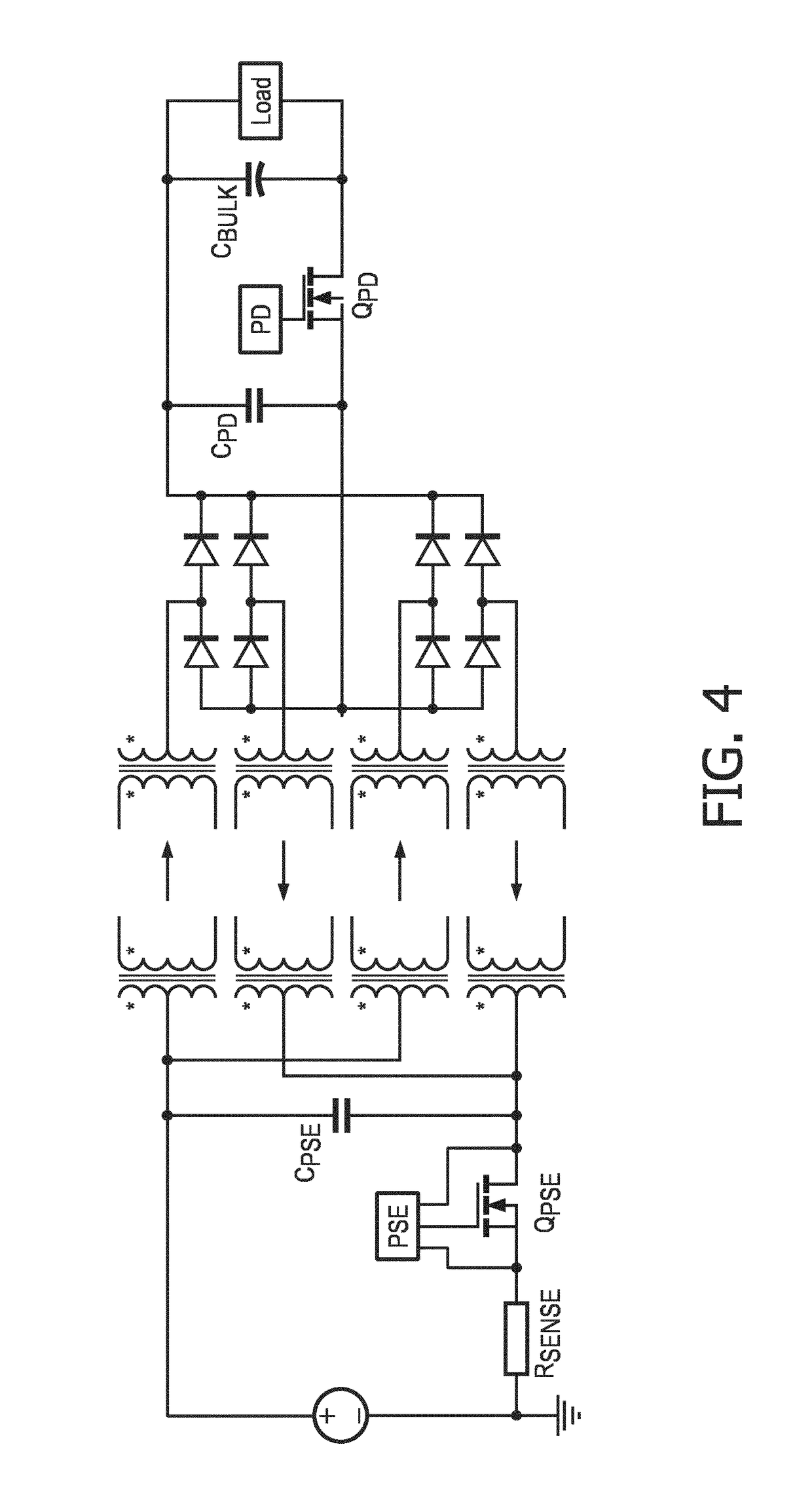
The invention relates to a power distribution system, such as a Power over Ethernet power distribution system. A powered device provides a pulse, such as a Maintain Power Signature, when in standby such that a power providing device remains providing power to it. To increase energy efficiency, the MPS can be cycled (60 ms pulse every 300 ms to 400 ms) according to the IEEE802.3af / at standards. By introducing a controllable switch, for electrically decoupling at least part of the powered device from the power providing device, and a pulse generator, the MPS can be generated in a more energy efficient way and / or can be shortened (e.g. to 5 ms). As an example, the controllable switch can decouple the bulk capacitor of the powered device during MPS generation to prevent the bulk capacitor from filtering out the MPS.

Description

CROSS-REFERENCE TO PRIOR APPLICATIONS[0001]This application is the U.S. National Phase application under 35 U.S.C. § 371 of International Application No. PCT / EP2015 / 050123, filed on Jan. 7, 2015, which claims the benefit of European Patent Application No. 14151164.2, filed on Jan. 14, 2014. These applications are hereby incorporated by reference herein.FIELD OF THE INVENTION[0002]The invention relates to a power distribution system comprising a power providing device for providing power and a powered device, such as a luminaire, to be powered by the power providing device. The invention further relates to the power providing device, the powered device, and a power distribution method and computer program product for distributing power within the power distribution system.BACKGROUND OF THE INVENTION[0003]According to the Power over Ethernet (PoE) Institute of Electrical and Electronics Engineers (IEEE) Standard 802.3af / at a powered device (PD) is powered by power sourcing equipment (...

Claims


Application Information

Patent Timeline
Patent Type & Authority Patents(United States)
IPC IPC(8): G06F1/26G06F1/3296H04L12/40G06F1/3206H04L12/10G06F1/32G06F1/3287H02J7/00
CPCG06F1/3287G06F1/266G06F1/3206G06F1/3296H04L12/40045H04L12/10Y02D50/20H02J2007/006Y02D10/171Y02D10/172H02J2207/30Y02D10/00Y02D30/50Y04S20/20Y02B70/30H02J3/02H02J3/06H02J7/00
Inventor YSEBOODT, LENNARTWENDT, MATTHIAS
Owner SIGNIFY HLDG BV
Learn More