Motion blur compensation

a compensation and motion technology, applied in the field of motion, can solve the problems of reduced computation time, scanner instability, and inability to process images acquired during motion, and achieve the effect of high frame rate and high resolution

Active Publication Date: 2019-02-26
3SHAPE AS
View PDF25 Cites 0 Cited by
  • Summary
  • Abstract
  • Description
  • Claims
  • Application Information

AI Technical Summary

Benefits of technology

[0028]In some embodiments, the in-focus position of a sensor element corresponds to the position of the focus plane in which the focus plane intersects a portion of the object surface and where the light rays returning from this portion of the object surface are imaged onto this particular sensor element. In embodiments, where a pattern is arranged to provide structure to the probe light, the in-focus position for a given sensor element may correspond to the position of the focus plane where the pattern is in focus on the object being scanned for this sensor element. The camera may record a high value of the correlation measure for that sensor element at the in-focus position, when the position of the focus plane is varied over a range of values.
[0197]For a static pattern a single sub-scan can be obtained by collecting a number of 2D images at different positions of the focus plane. As the focus plane coincides with the scan surface, the pattern will be projected onto the surface point in-focus and with high contrast. The high contrast gives rise to a large spatial variation of the static pattern on the surface of the object, thereby providing a large variation, or amplitude, of the pixel values over a group of adjacent pixels. For each group of pixels it is thus possible to identify individual settings of the focusing plane for which each group of pixels will be in focus. By using knowledge of the optical system used, it is possible to transform the contrast information vs. position of the focus plane into 3D surface information, on an individual pixel group basis.

Problems solved by technology

It remains a problem to provide motion blur compensation in 3D scanning, such as optical scanning, of objects in order to obtain excellent virtual 3D models of the scanned objects.
Motion sensors with limited accuracy can still provide a first guess for a software-based stitching / registration of partial scans based on, e.g., the Iterative Closest Point class of algorithms, resulting in reduced computation time.
Prior art does not provide for motion compensation in relation to a 3D scanner where focus plane images can be acquired while the handheld scanner, and thereby, sensor is moving, i.e. in prior art scanners focus plane images acquired during motion cannot be processed and used to obtain an assembled scan of an object.
If a focusing element is translated back and forth with a frequency of several Hz this may lead to instability of the scanner.
This may however, only substantially reduce the vibration to the first order.
If a counter-weight balanced device is rotated around the counter-weight balanced axis, there may be issues relating to the torque created by the counter-weights.
However, real time high resolution 3D scanning creates an enormous amount of data.

Method used


Image

  • Motion blur compensation
  • Motion blur compensation
  • Motion blur compensation

Examples


Embodiment Construction

[0240]In the following description, reference is made to the accompanying figures, which show by way of illustration how the invention may be practiced.

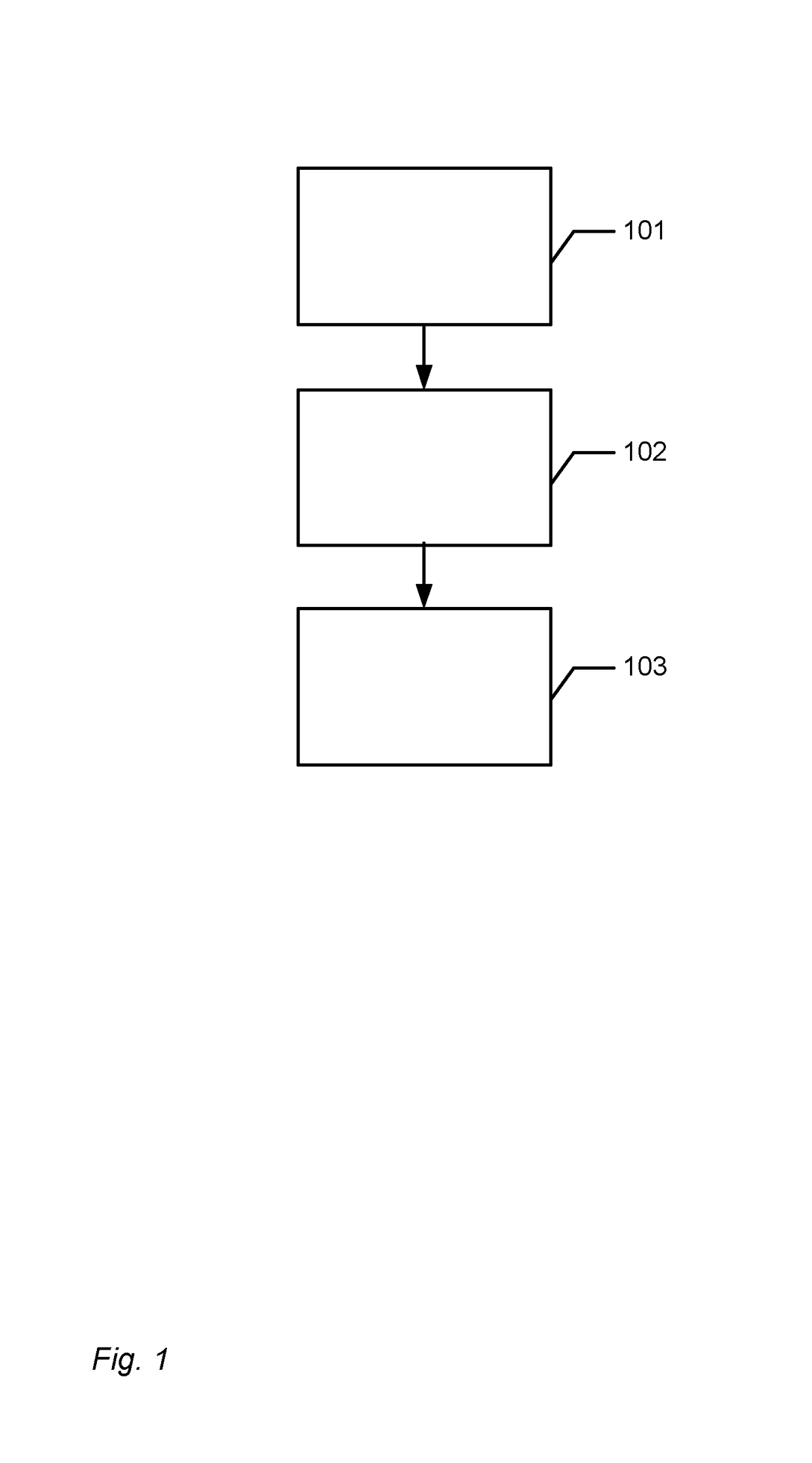
[0241]FIG. 1 shows a flowchart of a method for compensating for motion blur when performing a 3D scanning of at least a part of an object by means of a 3D scanner.

[0242]The motion blur occurs because the scanner and the object are moved relative to each other while the scanning is performed. The motion blur compensation comprises that:

[0243]In step 101 it is determined whether there is a relative motion between the scanner and the object during the acquisition of the sequence of focus plane images.

[0244]In step 102 a motion compensation based on the determined motion is performed, if a relative motion is determined.

[0245]In step 103 a 3D surface is generated from the sequence of focus plane images.

[0246]In some cases, a first 3D surface has been generated prior to steps 101-103 and the motion compensation in step 102 and / or the gener...


PUM


Abstract

Disclosed is a method for compensating for motion blur when performing a 3D scanning of at least a part of an object by means of a 3D scanner, where the motion blur occurs because the scanner and the object are moved relative to each other while the scanning is performed, and where the motion blur compensation comprises:—determining whether there is a relative motion between the scanner and the object during the acquisition of the sequence of focus plane images;—if a relative motion is determined, performing a motion compensation based on the determined motion; and—generating a 3D surface from the sequence of focus plane images.

Description

FIELD OF THE INVENTION[0001]This invention generally relates to a system and a method for compensating for motion blur. More particularly, the invention relates to motion blur compensation in 3D scanning of at least a part of an object by means of a 3D scanner.BACKGROUND OF THE INVENTION[0002]Motion blur compensation is generally known from 2D scanning or imaging of objects.[0003]It remains a problem to provide motion blur compensation in 3D scanning, such as optical scanning, of objects in order to obtain excellent virtual 3D models of the scanned objects.SUMMARY[0004]Disclosed is a method for compensating for motion blur when performing a 3D scanning of at least a part of an object by means of a 3D scanner, where the motion blur occurs because the scanner and the object are moved relative to each other while the scanning is performed, and where the motion blur compensation comprises:[0005]determining whether there is a relative motion between the scanner and the object during the ...

Claims


Application Information

Patent Timeline
Patent Type & Authority Patents(United States)
IPC IPC(8): A61C1/00G06K9/40H04N13/106G06T5/00G06T7/30G06T7/571G06T5/50A61C3/00H04N9/47H04N7/18
CPCH04N13/106G06T5/003G06T5/50G06T7/30G06T7/571G06T2207/30036G06T2207/10016G06T2207/10028G06T2207/10148G06T2207/20201H04N23/6812
Inventor FISKER, RUNEOJELUND, HENRIKVAN DER POEL, MIKEHANSEN, KRISTIAN EVERSGAARDE, ANDERS
Owner 3SHAPE AS
Why Eureka
Try Eureka