
Detachable tube coupling system

a technology of coupling system and detached tube, which is applied in the direction of couplings, mechanical equipment, etc., can solve the problems of limited incorporation of standard and metric configurations, rigid approach impose many limitations on the manufacturer and end user, so as to facilitate the swivel of thread modules and facilitate the sealing between the base and the coupling

Inactive Publication Date: 2019-03-05
OWEN RANDEL WILLIAM
View PDF5 Cites 2 Cited by
  • Summary
  • Abstract
  • Description
  • Claims
  • Application Information

AI Technical Summary

Benefits of technology

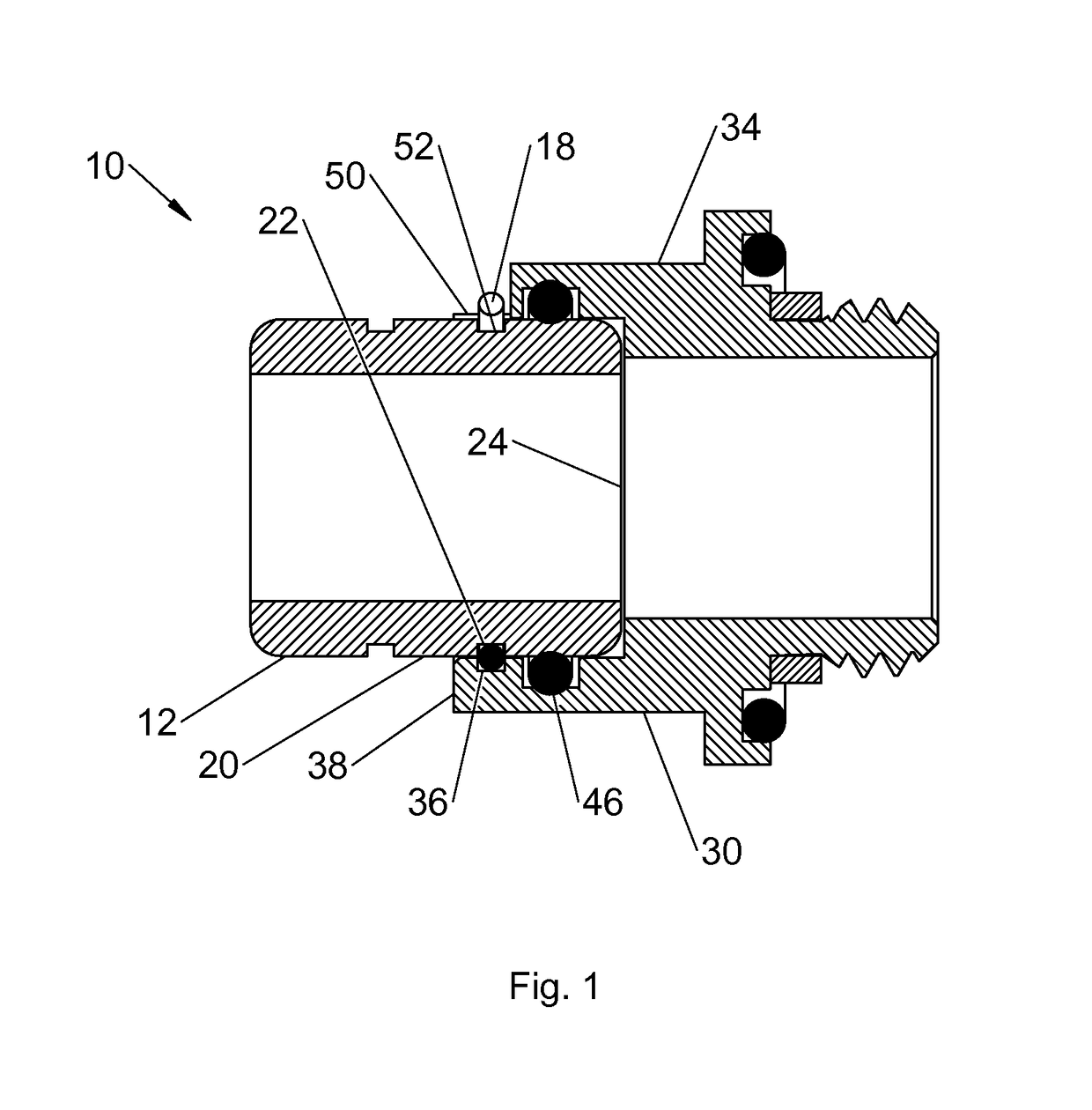
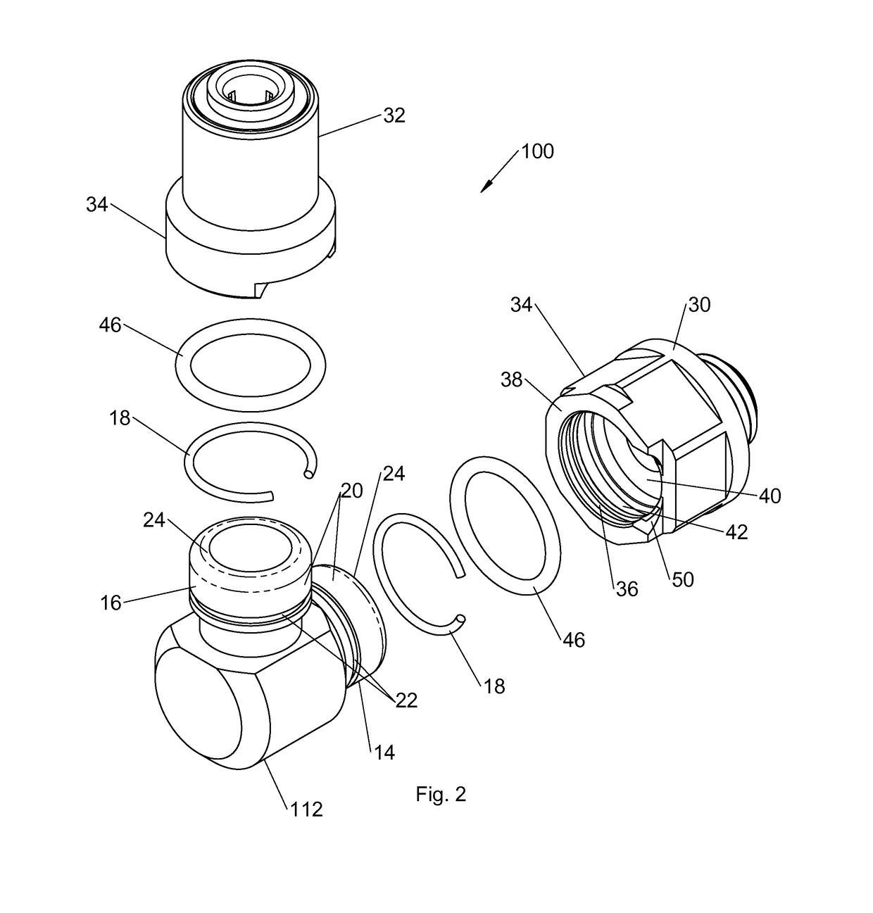
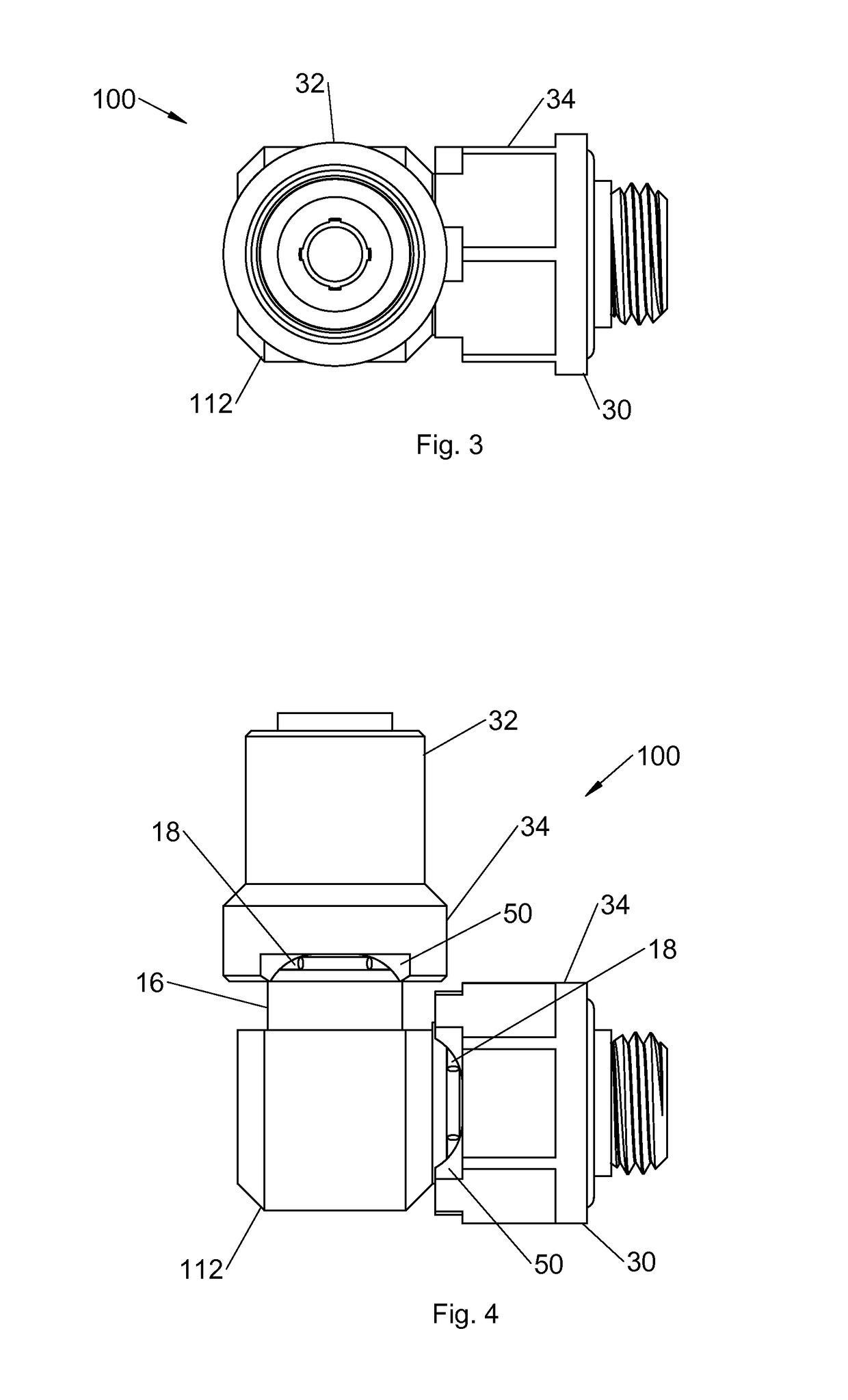
[0010]In view of the foregoing disadvantages inherent in the known types of detachable coupling systems now present in the prior art, the present invention provides an improved Detachable Tube Coupling System. As such, the general purpose of the present invention, which will be described subsequently in greater detail, is to provide a new and improved Detachable Tube Coupling System and method which has all the advantages of the prior art and none of the disadvantages. The present invention provides for a series of standard configuration base modules mechanically interfaced to interchangeable tube coupling modules and / or thread modules. In one embodiment, a mechanical interface seals and locks the coupling modules to the base modules. The seal between the base and coupling is facilitated by an O-ring. The locking feature is accomplished with a shared, machined groove, half of which resides in the base module and half in the tube / thread module. A flexible plastic or metal line engages the combined groove to lock the modules into position. The design additionally facilitates the thread modules to swivel as required for installation or removal. The design approach enables a large number of tube fitting configurations with a relatively limited number of interchangeable modules.
[0011]To attain this, the present invention essentially comprises a locking line fabricated of an inextensible, flexible, plastic or metal material and having a fixed diameter along the entire length. A base fitting formed with at least one end forming an inner tube having an exterior surface with a cylindrical configuration, and an interior surface with a cylindrical configuration. The inner tube having a free inner end with an interior groove having an annular semi-cylindrical configuration formed in the exterior surface. The interior groove is located at a fixed axial length from the free end of the inner tube. A modular coupler having at least one end forming an outer tube having an exterior surface with a cylindrical configuration, an interior surface with a cylindrical configuration and a free outer end. An exterior groove having an annular semi-cylindrical configuration is formed in the interior surface of the outer tube adjacent to the free end of the outer tube. An exterior notch is formed in the outer tube in communication with the interior groove, whereby when the inner tube and the outer tube are axially positioned with the interior groove and exterior groove forming a channel, the channel has a diameter essentially equal to the diameter of the locking line. The locking line is in a locked orientation when the central section is positioned within the channel to abate axial movement between the inner and outer tubes, the free ends are exterior of the system for handling and the intermediate sections located between the free ends and the central section of the locking lines are within the outer notch. The locking line is adapted to be pulled from the channel through the outer notch to an unlocked orientation thereby facilitating separation of the inner and outer tubes.

Problems solved by technology

This rigid approach imposes many limitations on the manufacturer and end user.
The incorporation of standard and metric configurations is uncommon and restricted.
While these devices fulfill their respective, particular objectives and requirements, the aforementioned do not describe Detachable Tube Coupling System having a detachable mechanical interface that seals and locks a series of coupling and base modules while providing a freely rotatable connection for easy installation or removal and facilitating a large number of configurations with a relatively limited number of interchangeable modules.

Method used


Image

  • Detachable tube coupling system
  • Detachable tube coupling system
  • Detachable tube coupling system

Examples


embodiment 200

[0046]In reference to FIG. 7, an alternate embodiment 200 is shown which includes abase fitting 212 configured as a straight connector. The base fitting having two free ends, each end forming an inner tube in a cylindrical configuration with annular grooves formed in the exterior surface of each of the inner tubes a fixed axial length from the free end. Two modular couplers are shown 30, 32 each having a free end having at least one end forming an outer tube 34 with an exterior in a cylindrical configuration, and an interior surface in a cylindrical configuration. A groove 36 is formed in the interior surface of each coupler having an annular semi-rectangular configuration and located adjacent to the free end of the outer tube. An exterior notch 50 is formed in the outer tube of each of the couplers in communication with the interior groove of each of the free ends of the inner tubes. A locking line 18 is threaded through the notches into the channels formed by the alignment of each...

embodiment 300

[0047]In reference to FIG. 8, an alternate embodiment 300 is shown which includes abase fitting 312 configured as a tee connector. The base fitting 312 having three free ends, each end forming an inner tube in a cylindrical configuration with annular grooves 22 formed in the exterior surface of each of the inner tubes a fixed axial length from the free ends 24. Three modular couplers are shown each having a free end having at least one end forming an outer tube with an exterior in a cylindrical configuration, and an interior surface in a cylindrical configuration. A groove is formed in the interior surface of each coupler having an annular semi-rectangular configuration and located adjacent to the free end of the outer tube. An exterior notch 50 is formed in the outer tube of each of the couplers in communication with the interior groove of each of the free ends of the inner tubes. A locking line 18 is threaded through the notches into the channels formed by the alignment of each of...


PUM


Abstract

A Detachable Tube Coupling System comprised of a plurality of base and coupling modules formed with a mechanical interface which includes a locking line, an inner tube and having an exterior surface with a circumferential interior groove, an O-ring and an outer tube formed with a circumferential interior groove in the interior surface and an exterior notch formed in the outer tube in communication with the interior groove.

Description

RELATED APPLICATION[0001]The present patent application claims priority to the corresponding provisional patent application Ser. No. 62 / 052,023, entitled “Detachable Tube Coupling System” filed on Sep. 18, 2014.BACKGROUND OF THE INVENTION[0002]Field of the Invention[0003]The present invention relates to a Detachable Tube Coupling System and more particularly pertains to a series of base fittings mechanically interfaced to modular tube couplings and / or thread modules by engaging a locking line in a shared groove between the base and tube and / or thread modules.[0004]Description of the Prior Art[0005]The use of detachable couplings is known in the prior art. More specifically, detachable couplings previously devised and used for the purpose of removably attaching and sealing plastic, elastomeric or metal tubing are known to consist basically of familiar, expected, and obvious structural configurations, notwithstanding the myriad of designs encompassed by the crowded prior art which has...

Claims


Application Information

Patent Timeline
Patent Type & Authority Patents(United States)
IPC IPC(8): F16L37/14
CPCF16L37/148
Inventor OWEN, RANDEL WILLIAM
Owner OWEN RANDEL WILLIAM
Learn More