
Damping force control device for vehicle

a control device and vehicle technology, applied in the direction of vehicle components, electrical steering, resilient suspensions, etc., can solve the problems of inability to suppress inability to prevent adverse effects, and inability to calculate based on detected vertical accelerations. to achieve the effect of suppressing changes in vehicle body posture, and reducing the risk of accidents

Inactive Publication Date: 2019-03-12
TOYOTA JIDOSHA KK
View PDF7 Cites 0 Cited by
  • Summary
  • Abstract
  • Description
  • Claims
  • Application Information

AI Technical Summary

Benefits of technology

This patent is about a device that controls the damping force in a vehicle to ensure a comfortable ride and prevent changes in the vehicle's posture. The device uses the vertical speeds of the vehicle, which are caused by both the road surface and the driver's operation, to calculate the target damping forces. These forces are used to control the vehicle's movement and prevent vibrations or unwanted changes in posture. The device also estimates the lateral and longitudinal accelerations of the vehicle, which are useful for controlling the vehicle's stability. By advancing the timing of these accelerations, the device reduces the likelihood of delays in estimating the second vertical speed, which is important for ensuring accurate control of the vehicle's movement. Overall, this device improves the vehicle's ride comfort and stability while avoiding excessive damping forces.

Problems solved by technology

In the above control (1), since the damping force control by the ride comfort control and the damping force control by the driving stability control are alternatively performed, it is impossible to suppress changes in posture of the vehicle body while securing good ride comfort in a situation, for example, where the steering operation is performed on a rough road.
In the above controls (2) and (3), since excessive damping forces are included in controlled variables of the damping forces as described in detail later, it is impossible to prevent occurrence of adverse effects such as the occurrence of high frequency vibrations of the vehicle body occurred due to extra damping forces.
Therefore, special detection devices such as vertical acceleration sensors for detecting vertical accelerations of the wheels and calculations based on detected vertical accelerations are unnecessary.

Method used


Image

  • Damping force control device for vehicle
  • Damping force control device for vehicle
  • Damping force control device for vehicle

Examples


first embodiment

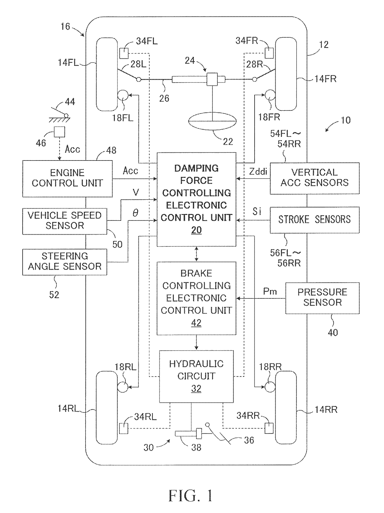
[0059]The damping force control apparatus 10 according to the first embodiment shown in FIG. 1 is applied to a vehicle 16 having a vehicle body 12 as a sprung mass and wheels 14FL, 14FR, 14RL and 14RR as unsprung masses. Shock absorbers 18FL, 18FR, 18RL and 18RR are mounted between the vehicle body 12 and the wheels 14FL, 14FR, 14RL and 14RR, respectively. The damping force control device 10 includes a damping force controlling electronic control unit 20 that controls damping coefficients CFL, CFR, CRL and CRR of the shock absorbers 18FL, 18FR, 18RL and 18RR.

[0060]The shock absorbers 18FL, 18FR, 18RL and 18RR are damping force variable shock absorbers having a plurality of control stages S. The control stages S take n (positive integer) steps ranging from the control stage S1 (soft) having the smallest damping coefficient Ci (i=FL, FR, RL and RR) to the control stage Sn (hard) having the largest damping coefficient Ci. The shock absorbers 18FL to 18RR generate damping forces represe...

second embodiment

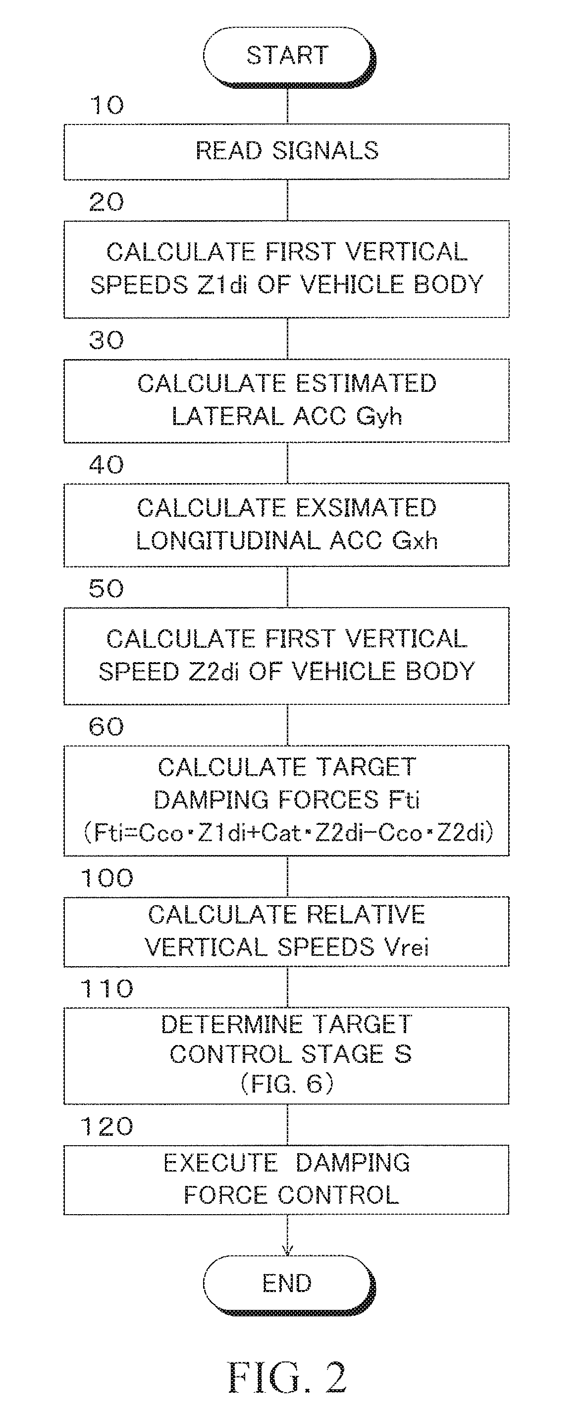
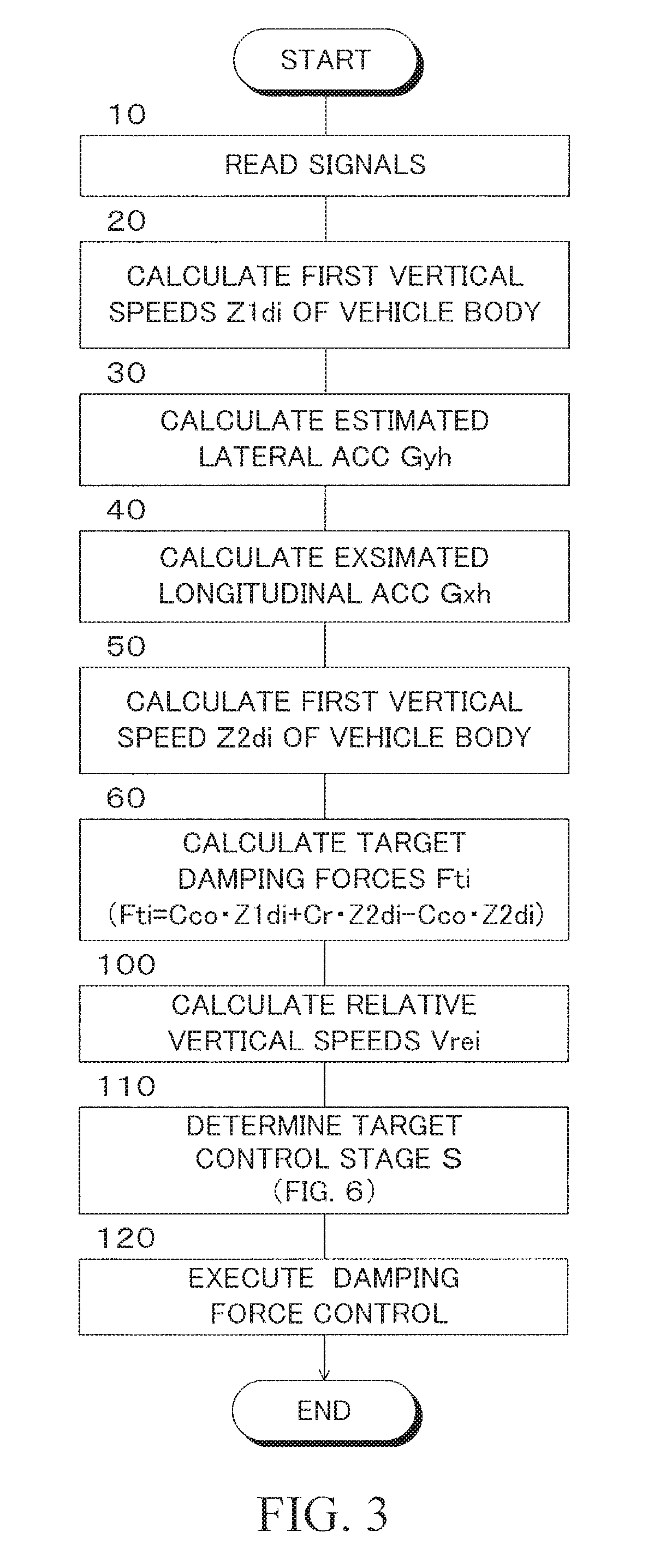
[0083]The second embodiment is configured as a modification example of the first embodiment, and the damping force control in the second embodiment is performed according to the flowchart shown in FIG. 3. In FIG. 3, the same step numbers as those shown in FIG. 2 are assigned to the same steps as those shown in FIG. 2. This also applies to other embodiments to be described later.

[0084]Steps 10 to 30 and steps 100 to 120 are executed in the same manners as in the first embodiment. Step 40 in the first embodiment is not executed. When step 30 is completed, in a step 50, estimated vertical accelerations Z2ddi of the vehicle body 12 at the positions of the wheels 14FL to 14RR 12 are calculated in a manner known in the art based on the estimated longitudinal acceleration Gxh of the vehicle. Further, the second vertical speeds Z2di of the vehicle body at the positions of the wheels 14FL to 14RR caused by the driver's steering operation are calculated by integrating the estimated vertical a...

third embodiment

[0088]The third embodiment is also configured as a modification example of the first embodiment, and the damping force control in the third embodiment is performed according to the flowchart shown in FIG. 4.

[0089]Steps 10, 20, 40 and 100 to 120 are executed in the same manners as in the first embodiment. Step 30 in the first embodiment is not executed. When step 40 is completed, in a step 50, estimated vertical accelerations Z2ddi of the vehicle body 12 at the positions of the wheels 14FL to 14RR are calculated in the manner known in the art based on the estimated longitudinal acceleration Gxh of the vehicle. Furthermore, second vertical speeds Z2di of the vehicle body 12 at the positions of the wheels 14FL to 14RR caused by driver's acceleration / deceleration operation are calculated by integrating the estimated vertical accelerations Z2ddi.

[0090]When step 50 is completed, step 70 is executed instead of step 60 in the first embodiment. In step 70, the target damping forces Fti (i=F...


PUM


Abstract

A damping force control device for controlling damping forces of shock absorbers by a control device, which is configured to to estimate first vertical speeds at the positions of wheels based on the vertical accelerations of a vehicle body at the positions of the wheels, to estimate second vertical speeds of the vehicle body caused by driver's driving operation based on driving operation amount of the driver, to calculate target damping forces by subtracting products of damping coefficients of the ride comfort control and second vertical speeds from the sums of products of the damping coefficients of the ride comfort control and first vertical speeds and products of damping coefficients for controlling posture change of the vehicle body and the second vertical speeds, and to control damping coefficients of the shock absorbers based on the target damping forces.

Description

CROSS-REFERENCE TO RELATED APPLICATION[0001]The disclosure of Japanese Patent Application NO. JP2016-100744 filed on May 19, 2016 is incorporated by reference in its entirety.BACKGROUND1. Technical Field[0002]The present disclosure relates to a damping force control device for a vehicle such as an automobile.2. Description of the Related Art[0003]A damping force control in a vehicle such as an automobile includes a ride comfort control for improving a ride comfort of the vehicle by damping vertical vibrations of a vehicle body caused by inputs from a road surface, and a driving stability control for suppressing a change in posture of the vehicle body caused by driver's operation, i.e., steering, acceleration or deceleration. The damping force control is achieved by controlling damping coefficients of shock absorbers mounted between sprung and unsprung masses corresponding to wheels to target damping coefficients.[0004]However, since the frequency ranges and amplitudes of the vertica...

Claims


Application Information

Patent Timeline
Patent Type & Authority Patents(United States)
IPC IPC(8): B60G17/0195B60G17/016B62D5/04
CPCB60G17/0195B62D5/0472B60G17/0164B60G17/0162B60G17/015B60G17/06B60G2400/102B60G2400/204B60G2400/252B60G2400/41B60G2400/51B60G2500/10
Inventor TSUMANO, MITSUHIRO
Owner TOYOTA JIDOSHA KK
Learn More