Transient liquid phase sinter pastes and application and processing methods relating thereto

a liquid phase sintering and liquid phase technology, applied in the direction of manufacturing tools, welding/cutting media/materials, welding apparatus, etc., can solve the problems of reducing the system time-to-failure, melting of the attaching material, interconnect failure is a major obstacle, etc., to achieve high application temperature limits, excellent durability, and superior microstructure

Active Publication Date: 2019-03-19
UNIV OF MARYLAND
View PDF1 Cites 1 Cited by
  • Summary
  • Abstract
  • Description
  • Claims
  • Application Information

AI Technical Summary

Benefits of technology

[0020]In some implementations, nickel-tin (Ni—Sn) and nickel-copper-tin (Ni—Cu—Sn) sinter pastes are provided as an interconnect material for TLPS sinter joints in electronic systems. The disclosed pastes exhibit superior microstructures, extremely high application temperature limits, and excellent durability as compared to conventional interconnect technologies.

Problems solved by technology

However, interconnect failure is a major obstacle in the design of reliable electronic systems (McCluskey, P.
Harsh environments coupled with growing power densities lead to higher joint temperatures that soften conventional attach materials, making them susceptible to fatigue and reducing their system time-to-failure or in extreme cases, leading to melting of the attach material.
Conventional attach materials utilized in power electronics were developed for application temperatures between about 100° C. and 150° C. Such conventional attach materials include solders with melting temperatures (Tm) in the range of between about 200° C. to 300° C. As such, they are not suitable for applications at elevated temperature conditions (e.g., such as 200° C. or higher).
In automotive applications, the integration of microelectronic systems in the engine compartment, referred to as the under-the-hood environment, increases thermal load on such systems due to heat dissipated by the engine during operation.
However, additional cost as well as increased weight and volume requirements are associated with these efforts.
Traditional Si devices are limited to relatively low voltage operation, and are not suitable for use at temperatures above 175° C. due to their material properties as a low band-gap semiconductor.
It is, however, this operation at higher temperature that has created a major packaging challenge.
Packaging and interconnect technologies applied in conventional microelectronic systems were developed for traditional Si-based devices, which are limited to relatively low temperature applications (e.g., temperatures below 200° C.)
However, they have a melting temperature (Tm) of 183° C., which is far too low for high temperature applications.
Additionally, eutectic Sn37Pb solders show relatively high creep rates at elevated temperatures and are subject to many regulatory restrictions.
As such, they are not suitable for many applications.
However, similar to other lead (Pb)-based solders, they are highly ductile and soften close to their Tm, limiting their fatigue life.
Bi—Ag alloys, while less conventional, are another reflow solder interconnect, which possess liquidus temperatures of 262° C. However, they exhibit brittle behavior with limited ductility and elongation.
Such problems can be slightly mitigated by increased ratios of silver (Ag), but at substantially higher cost.
Moreover, they possess limited wetting capabilities and low thermal conductivities.
As such, Bi—Ag solders have not proven reliable or efficient for many applications.
As such, their availability has been substantially reduced due to the shrinking market and the possibility they will be entirely restricted by future regulations (e.g., such as the Restriction of Hazardous Substances Directive).
Moreover, they require relatively high processing temperatures, and exhibit high creep rates at elevated temperatures.
Moreover, relatively high costs are associated with these alloys, which inhibit their use in many applications.
However, such alloys also require relatively high process temperatures, with complicated and expensive processing techniques.
Suitable interconnect materials and processing techniques therefore remain a major challenge in the design of reliable high-temperature packages for power electronic devices and systems.
Established solder technologies have failed to overcome such problems and to provide for reliable high temperature operation.

Method used


Image

  • Transient liquid phase sinter pastes and application and processing methods relating thereto
  • Transient liquid phase sinter pastes and application and processing methods relating thereto
  • Transient liquid phase sinter pastes and application and processing methods relating thereto

Examples


Embodiment Construction

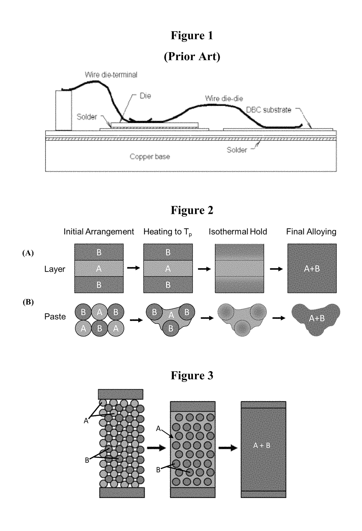
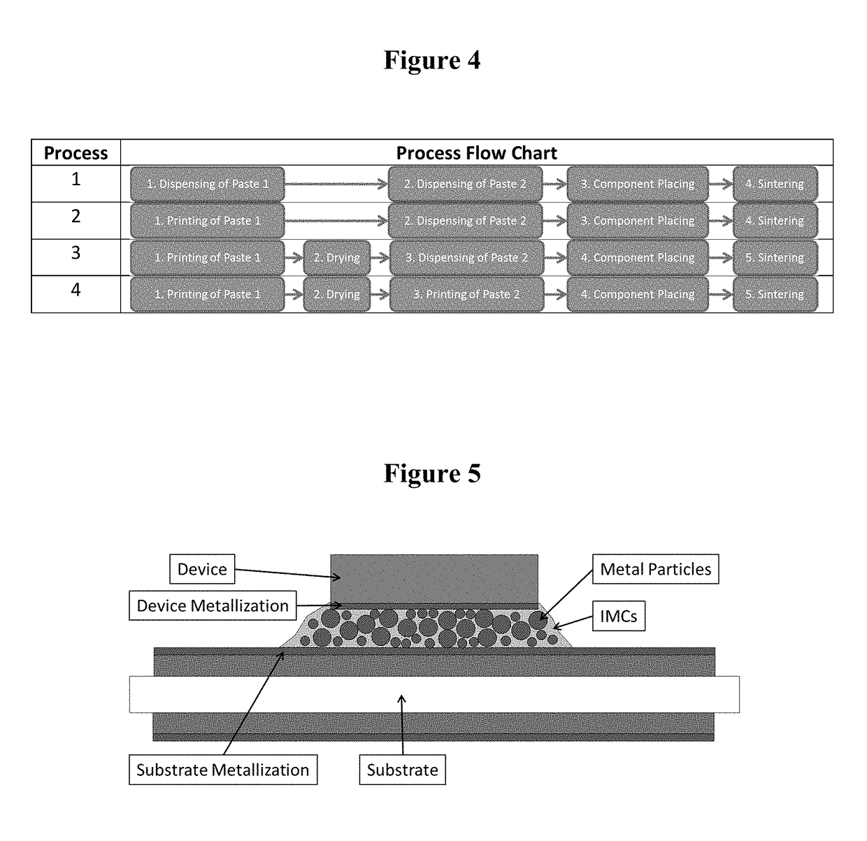
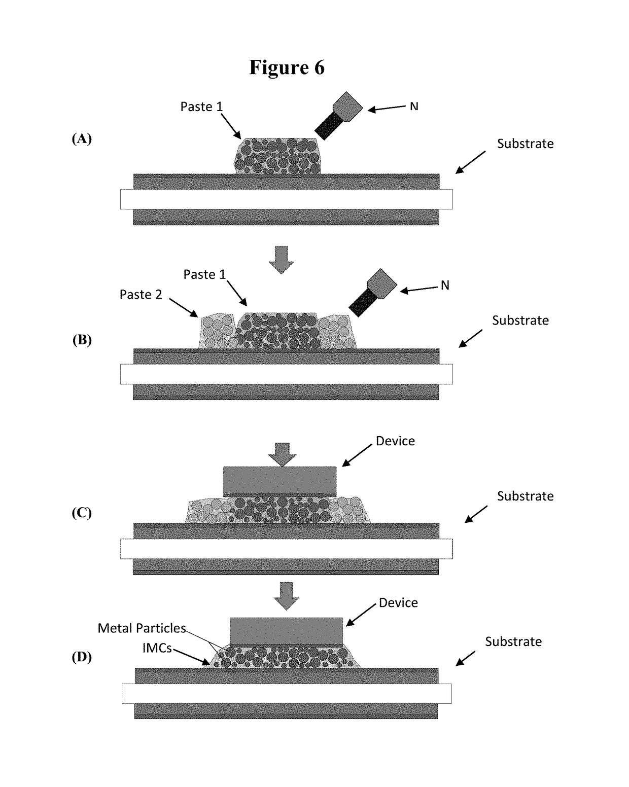
[0057]The present invention is directed to interconnect materials, and applications and processes for interconnect materials. In accordance with disclosed embodiments, Cu—Ni—Sn-based transient liquid phase sinter pastes are provided for use in electronic interconnects or joints. Transient liquid phase sintering (TLPS) may be used to form joints at relatively low process temperatures. The joints comprise intermetallic compounds (IMCs) which, due to a melting temperature shift during processing, may be utilized at relatively high temperatures. In addition, the resulting joints also preferably comprise, in addition to the formed IMCs, intact high melting temperature particles that were not consumed during the sintering process. The presence of such high melting temperature particles in combination with the formed IMCs substantially increases joint strength. The disclosed TLPS sinter pastes and processes provide for reliable interconnection in electronic systems, exhibiting superior str...


PUM

PropertyMeasurementUnit
melting temperatureaaaaaaaaaa
pressureaaaaaaaaaa
temperatureaaaaaaaaaa

Abstract

The present invention relates to transient liquid phase sinter pastes for electronic interconnects, and sinter paste application and processing methods.

Description

CROSS-REFERENCE TO RELATED APPLICATIONS[0001]This application is based on U.S. Provisional Patent Application Ser. No. 62 / 078,592, entitled “Cu—Ni—Sn-Based Transient Liquid Phase Sinter Paste and Process for Joining Using this Paste,” filed Nov. 12, 2014, which application is incorporated herein by reference in its entirety and to which priority is claimed.FIELD OF THE INVENTION[0002]The present invention relates to transient liquid phase sinter pastes for electronic interconnects, and sinter paste application and processing methods.BACKGROUND OF THE INVENTION[0003]Electronic systems are increasingly used in harsh environments under elevated thermal conditions. This includes applications and products subject to high absolute temperatures as well as very large temperature swings, such as for example deep well drilling (e.g., geothermal, oil or natural gas), military and aerospace, and automotive applications and products.[0004]The secure interconnection of electronic components and m...

Claims


Application Information

Patent Timeline
Patent Type & Authority Patents(United States)
IPC IPC(8): B23K35/02B23K1/00C22C13/00B23K35/26
CPCB23K35/025C22C13/00B23K35/262B23K1/0016H01L24/27H01L24/29H01L24/49H01L24/73H01L24/743H01L24/83H01L24/92H01L2224/05639H01L2224/05647H01L2224/05655H01L2224/27312H01L2224/2732H01L2224/2782H01L2224/27848H01L2224/27901H01L2224/29078H01L2224/29082H01L2224/291H01L2224/29286H01L2224/2929H01L2224/29298H01L2224/29311H01L2224/29339H01L2224/29347H01L2224/29355H01L2224/29499H01L2224/32225H01L2224/48227H01L2224/48472H01L2224/49109H01L2224/73265H01L2224/743H01L2224/83192H01L2224/83194H01L2224/83439H01L2224/83447H01L2224/83455H01L2224/83825H01L2224/92247H01L2924/00014H01L2924/00012H01L2224/45099H01L2924/014H01L2924/0105H01L2924/01029H01L2924/01047H01L2924/01028H01L2924/00
Inventor GREVE, HANNESMCCLUSKEY, F. PATRICK
Owner UNIV OF MARYLAND
Why Eureka
Try Eureka