
Synthetic aperture radar

a synthetic aperture radar and radar technology, applied in the direction of radio wave reradiation/reflection, using reradiation, measurement devices, etc., can solve the problems of difficult to accurately recognise objects present in the resulting images, image subject to geometric distortion, and difficulty in recognising objects in sar imagery, etc., to achieve simple object recognition, alter the aspect ratio of the image, and the effect of reducing the distortion

Active Publication Date: 2019-03-19
THALES HLDG UK
View PDF7 Cites 4 Cited by
  • Summary
  • Abstract
  • Description
  • Claims
  • Application Information

AI Technical Summary

Benefits of technology

This patent describes a way to make objects in synthetic aperture radar (SAR) imaging easier to recognize. This is done by manipulating the shadow and the layover caused by the object, which can be done by altering the aspect ratio of the image and reflecting or rotating it. The aspect ratio can be adjusted based on information about the SAR geometry. The technical effect of this patent is to improve the accuracy and reliability of SAR imaging for various applications such as navigation, surveillance, and emergency response.

Problems solved by technology

As the distance to objects is measured in the slant-range, rather than the true horizontal distance along the ground, the resulting images are subject to geometric distortions.
One such geometric distortion is the effect of layover.
Owing to the nature and geometry of SAR images, recognition of objects in SAR imagery is more challenging than in optical imagery.
However, it can be difficult to accurately recognise objects present in the resulting images.

Method used


Image

  • Synthetic aperture radar
  • Synthetic aperture radar
  • Synthetic aperture radar

Examples


Embodiment Construction

[0021]Specific embodiments will now be described, by way of example only and with reference to the accompanying drawings having the figure numbers as listed above.

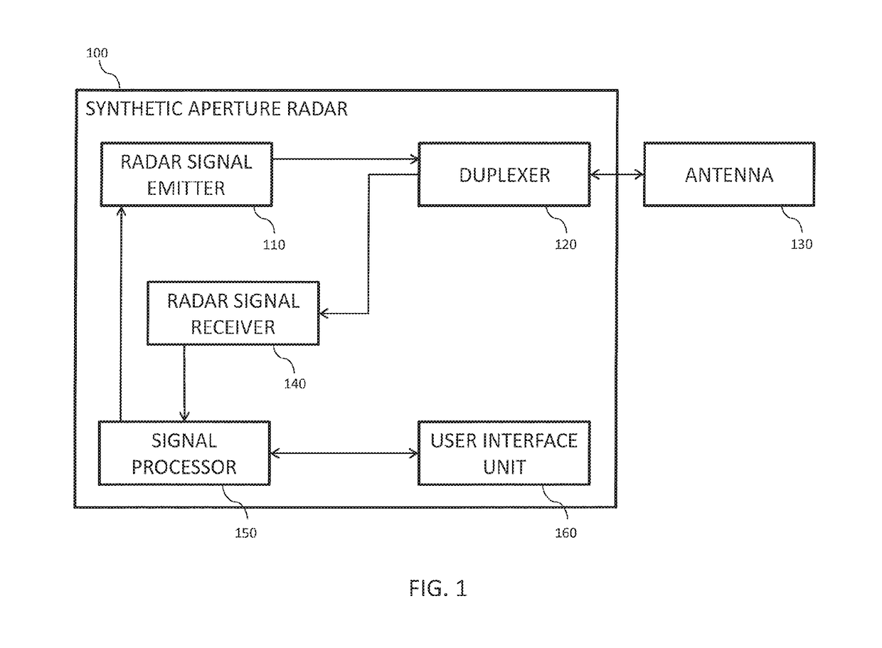
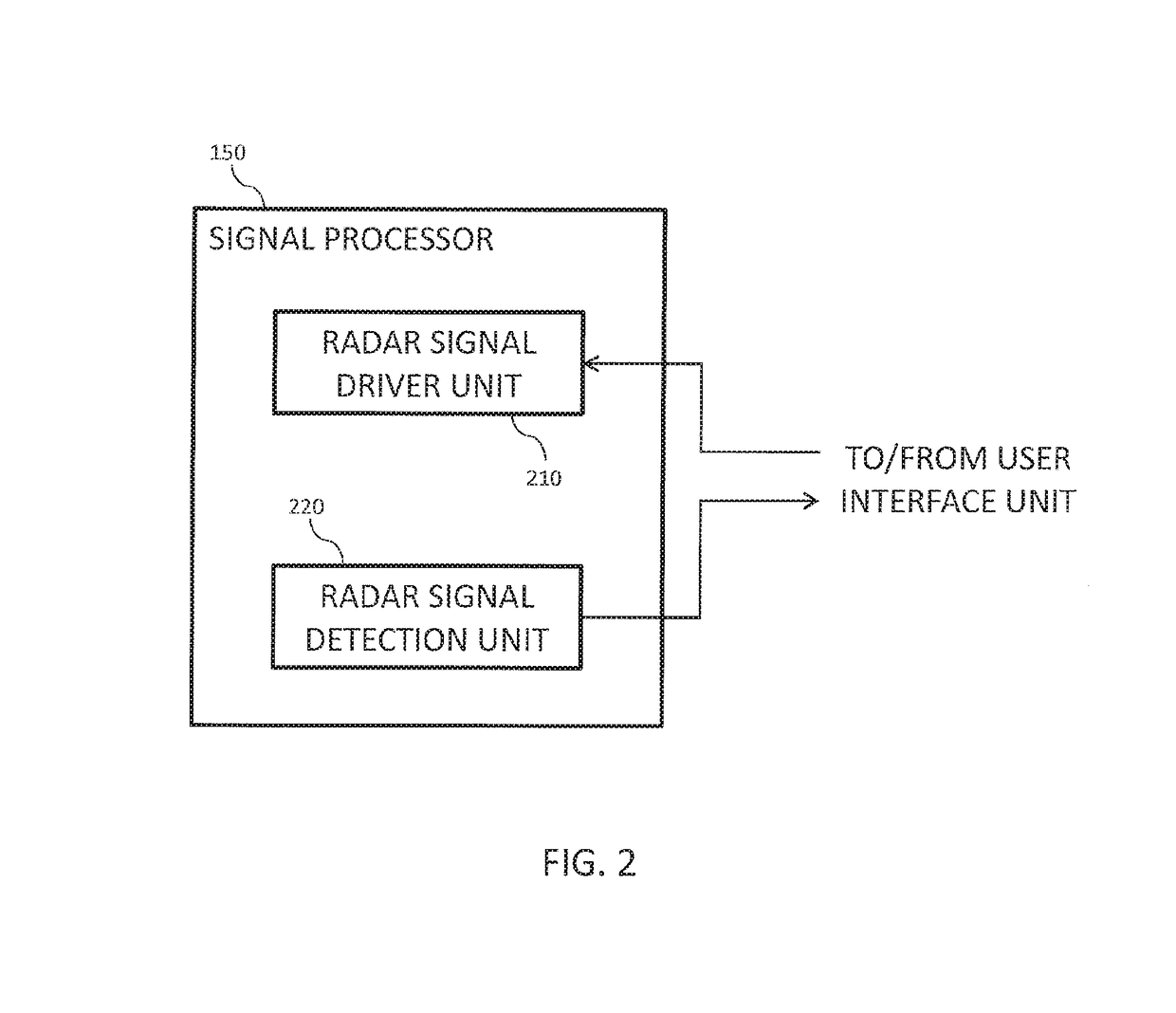
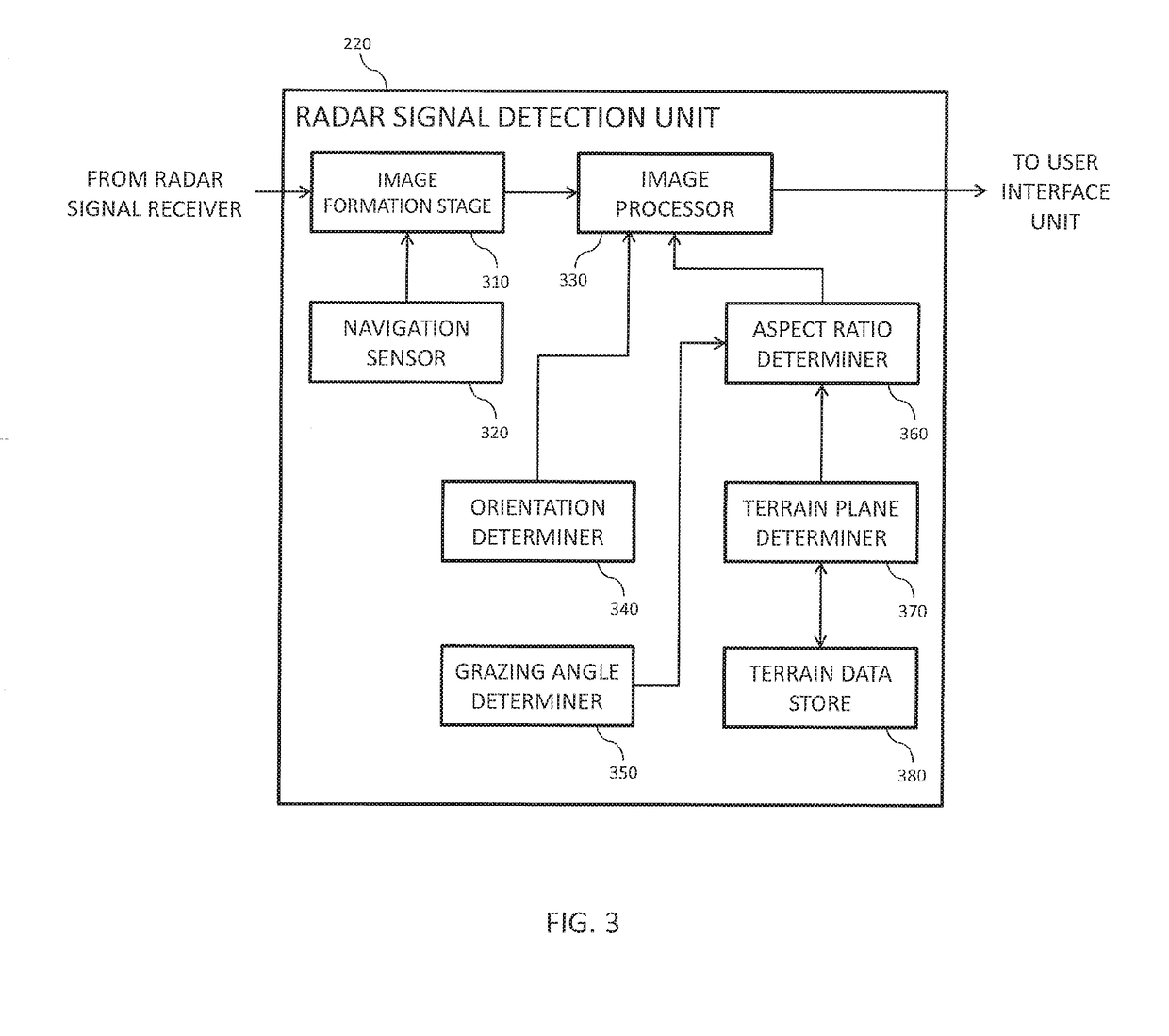
[0022]FIG. 1 illustrates a synthetic aperture radar 100. The synthetic aperture radar 100 is configured for mounting on a moving platform, which may comprise an airborne platform. The synthetic aperture radar 100 includes a radar signal emitter 110, which is configured to emit signals of sufficient bandwidth to achieve the desired slant-range resolution. The signals emitted from the radar signal emitter 110 are sent, via a duplexer 120, to an antenna 130 capable of illuminating an area of interest. Pulses of electromagnetic radiation are then transmitted from the antenna 130 for illumination of the area of interest.

[0023]The reader will appreciate that the form of the antenna 130 is not material to the description of the present embodiment. In one example, the antenna 130 is implemented by means of an array, but other type...


PUM


Abstract

Embodiments described herein simplify the recognition of objects in synthetic aperture radar (SAR) imagery. This may be achieved by processing the image in order to make the shadow caused by the object appear more similar to the object. Alternatively, this may be achieved by processing the image in order to make the layover caused by the object appear more similar to the object. Manipulation of the shadow caused by the object and the layover caused by the object may comprise altering the aspect ratio of the image, and in the case of manipulating the shadow caused by the image, may further comprise transforming the image by reflection or rotation. The aspect ratio of the image may be altered based on information about the image collection geometry, obtained by the SAR.

Description

CROSS-REFERENCE TO RELATED APPLICATIONS[0001]This application claims priority to, and the benefit of United Kingdom Application No. GB 1507829.8, filed on May 7, 2015, which is hereby incorporated by reference in its entirety.FIELD[0002]Embodiments of the disclosure herein describe techniques for processing synthetic aperture radar imagery.BACKGROUND[0003]Synthetic aperture radar (SAR) exploits the motion of an airborne antenna in order to simulate a large antenna electronically. In conventional radar systems, the resolution of the resulting image increases with the size of the antenna. An advantage of SAR is the ability to achieve high image resolutions with a comparatively small antenna.[0004]In SAR, the radar measures distances in slant-range by observing the time taken for an emitted signal to be reflected back to the radar from an object or the ground. As the distance to objects is measured in the slant-range, rather than the true horizontal distance along the ground, the resul...

Claims


Application Information

Patent Timeline
Patent Type & Authority Patents(United States)
IPC IPC(8): G01S13/90G01S7/41
CPCG01S13/9035G01S13/90G01S7/41G01S13/904G01S13/9027
Inventor STEVENS, MALCOLM
Owner THALES HLDG UK
Learn More