Rotor for an electric machine

a technology for electric machines and rotors, which is applied in the direction of dynamo-electric machines, magnetic circuit rotating parts, magnetic circuit shapes/forms/construction, etc., can solve the problems that cannot be put to practical use with the usual structures envisaged, and achieve the stability of the rotor to be further improved, high degree of flexibility in the production of the rotor, and low cost

Inactive Publication Date: 2019-03-19
SIEMENS AG
View PDF35 Cites 0 Cited by
  • Summary
  • Abstract
  • Description
  • Claims
  • Application Information

AI Technical Summary

Benefits of technology

[0013]For the first time the invention enables an electric machine to be equipped with a permanently excited rotor which may not only be equipped with rare earth magnets, but also with alternative magnets such as ferrite magnets or the like, wherein the major forces known from the use of rare earth magnets can be obtained at the same time. This is essentially achieved as a result of the poles of the magnets no longer being aligned in the direction of the air gap but transversely, i.e. parallel to a surface of the rotor facing the stator of the electric machine, in contrast to the prior art. By means of the pole shoe, the magnetic flux provided by the magnets is deflected in the direction of the stator. This structure thus enables magnets with virtually arbitrary dimensions to be incorporated into the rotor of the electric machine. This also makes it possible to use weaker magnets with regard to rare earth magnets, in particular, ferrite magnets, wherein at the same time the performance-related properties of the electric machine can essentially be retained.
[0039]With the invention an electric machine with a stator and a rotor are also proposed, wherein—as previously described—the rotor is designed according to the invention. This makes it possible to achieve an inexpensive, powerful electric machine. In particular, the use of rare earth magnets can be reduced or even avoided.

Problems solved by technology

Due to the high costs of such magnets, such machines are therefore only used in special cases for which such an investment can be adequately justified.
It has been shown that compared to rare earth magnets, ferrite magnets have a substantially lower energy density, that is to say, they provide a lower magnetic flux, and—for example, due to the large dimensions required—cannot be put to practical use with the usual structures envisaged.

Method used


Image

  • Rotor for an electric machine
  • Rotor for an electric machine

Examples


Embodiment Construction

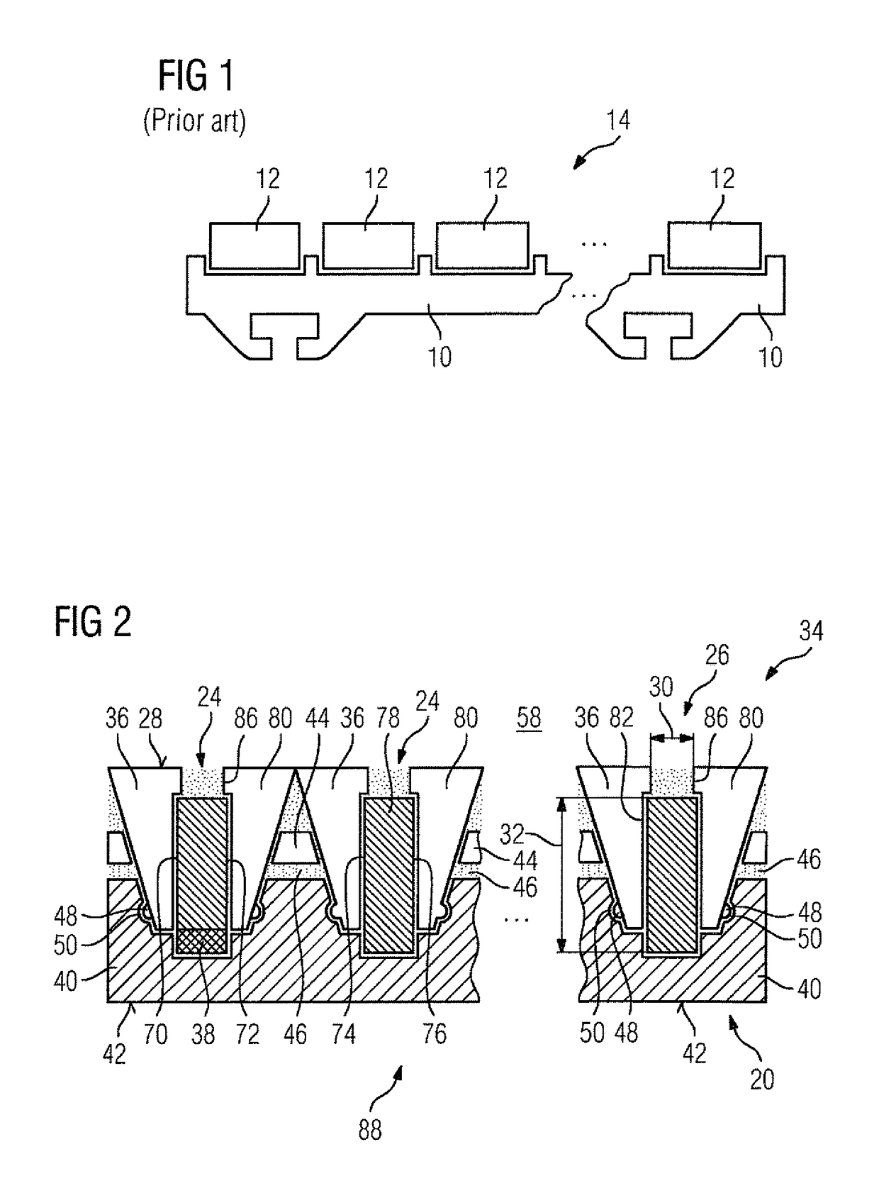
[0046]FIG. 1 is a diagrammatic side view of a section of a rotor embodied as a rotor 14 of a rotating electric machine of the prior art not shown in further detail. The rotor 14 has a rotor segment arrangement which is not described, of which part of a rotor segment is shown diagrammatically in a side view in FIG. 1. For further simplification, the curve in FIG. 1 is likewise not shown.

[0047]The rotor segment has a support structure 10 which is fitted with rod-shaped rare earth magnets 12 on its surface facing the stator. The poles of the rare earth magnets 12 are radially aligned, that is to say, one pole of one magnet 12 is facing the air gap in each case, wherein adjacent magnets 12 alternate in the direction of movement of the north and south pole. The installation of the rotor 14 in the electric machine and the mode of action of this known machine are not dealt with here, particularly as the person skilled in the art is sufficiently familiar with them.

[0048]FIG. 2 shows a secti...


PUM


Abstract

A rotor for an electric machine, comprising a modular design consisting of a plurality of modular elements is disclosed. These modules are arranged adjacent to each other in a direction of movement of the rotor. Each modular element has at least one magnet and at least one ferromagnetic pole shoe, and the poles of the magnet are aligned in the direction of movement of the rotor. An electric machine comprising a stator and a rotor according to the invention is also disclosed.

Description

CROSS-REFERENCES TO RELATED APPLICATIONS[0001]This application is the U.S. National Stage of international Application No. PCT / EP2013 / 067659, filed Aug. 27, 2013, which designated the United States and has been published as International Publication No. WO 2014 / 166554 A1 and which claims the priority of European Patent Application, Serial No. 13162732.5, filed Apr. 8, 2013, pursuant to 35 U.S.C. 119(a)-(d).BACKGROUND OF THE INVENTION[0002]The present invention relates to a rotor for an electric machine and an electric machine with a stator and a rotor.[0003]Electric machines of this type with movable units in the form of rotors are known in the prior art in principle, obviating the need for separate documentary evidence. In principle, a stator is provided for a rotating electric machine which as a rule provides an essentially circular aperture for receiving a rotor designed as a rotor. The rotor can be pivoted in the aperture, an air gap being formed between the rotor and the stator...

Claims


Application Information

Patent Timeline
Patent Type & Authority Patents(United States)
IPC IPC(8): H02K1/30H02K1/27
CPCH02K1/30H02K1/2773H02K1/2706
Inventor DORFNER, MATTHIASMATSCHEKO, GERHARD
Owner SIEMENS AG
Why Eureka
Try Eureka