Process for producing (meth)acrylic acid

a technology of acrylic acid and process, applied in the field of production of (meth)acrylic acid, can solve the problems of increasing the number of distillation columns and their associated energy costs, and increasing the cost of production

Active Publication Date: 2019-03-26
ARKEMA FRANCE SA
View PDF11 Cites 3 Cited by
  • Summary
  • Abstract
  • Description
  • Claims
  • Application Information

AI Technical Summary

Benefits of technology

[0055]The process according to the invention produces a stream of (meth)acrylic acid without producing aqueous discharges, and does not require the use of an azeotropic solvent in order to eliminate the water from the process. The process according to the invention also contributes to limiting the losses of (meth)acrylic acid at the top of the dehydration column.
[0073]The present invention makes it possible to overcome the drawbacks of the prior art linked to the use of a solvent-free recovery / purification process that requires a purified (meth)acrylic acid to be obtained.

Problems solved by technology

The complexity of the gas mixture obtained in this process makes it necessary to carry out a set of operations for recovering the acrylic acid contained in this gaseous effluent and convert it to a grade of acrylic acid that is compatible with the final use thereof, for example the production of acrylic acid polymers, or the production of acrylic ester polymers.
Nevertheless, a very significant economic problem is faced, mainly due to the expensive energy needed for eliminating the water used as acrylic acid absorption solvent, in so far as the effective elimination of the water without excessive loss of (meth)acrylic acid is complicated by the existence of interactions (hydrogen bonds) between the two compounds.
Thus, this separation operation is generally carried out on the industrial scale by distillation with a third azeotropic solvent, which contributes to increasing the number of distillation columns and their associated energy costs.
Moreover, the increase in the number of distillation columns leads to an additional cost linked to the supplementary consumption of polymerization inhibitors that must be introduced into each of said columns in order to purify the desired product and eliminate the by-products while preventing the problems of fouling of the equipment by polymerization of the monomer.
One alternative to this process that uses water as acrylic acid absorption solvent is to use a hydrophobic heavy solvent to extract the acrylic acid, but such a process does not simplify the acrylic acid purification process.
One drawback of this process is that the introduction of external water as absorption solvent makes it difficult to eliminate the water at the top of the absorption column without a significant loss of acrylic acid, and to recover a quality of crude acrylic acid having a low concentration of water as a sidestream, when this process is carried out in a two-column configuration.
Despite the advantages that the process described in document EP 2 066 613 provides, there still remain drawbacks linked to the implementation thereof.
In particular, at the top of the finishing column which functions under vacuum, the condenser releases residual vapours comprising organic impurities that must be eliminated, for example by incineration, which is harmful for the environment.
These systems are not suitable for reducing the operating pressure of the finishing column of a solvent-free (meth)acrylic acid purification process, such as that described in document EP 2 066 613.
Such systems, for example described in document U.S. Pat. No. 6,677,482 or 7,288,169, use steam and generate a large amount of aqueous effluents containing acrylic acid and organic impurities, which cannot be economically recycled to the purification loop formed by the dehydration column and the finishing column.
Indeed, it has been observed that the recycling of too large an amount of water at the dehydration column leads to sizeable losses of acrylic acid at the top of this column, unless an oversized column is used but this leads to an expensive investment.
These aqueous effluents therefore need to be sent to a water treatment plant or directly to a thermal oxidizer, thus giving rise on the one hand to a loss of high quality product and on the other hand to an environmentally harmful discharge.

Method used


Image

  • Process for producing (meth)acrylic acid
  • Process for producing (meth)acrylic acid

Examples


example 1 (

According to the Invention)

[0135]Simulations using ASPEN software have been used to illustrate the process according to the invention.

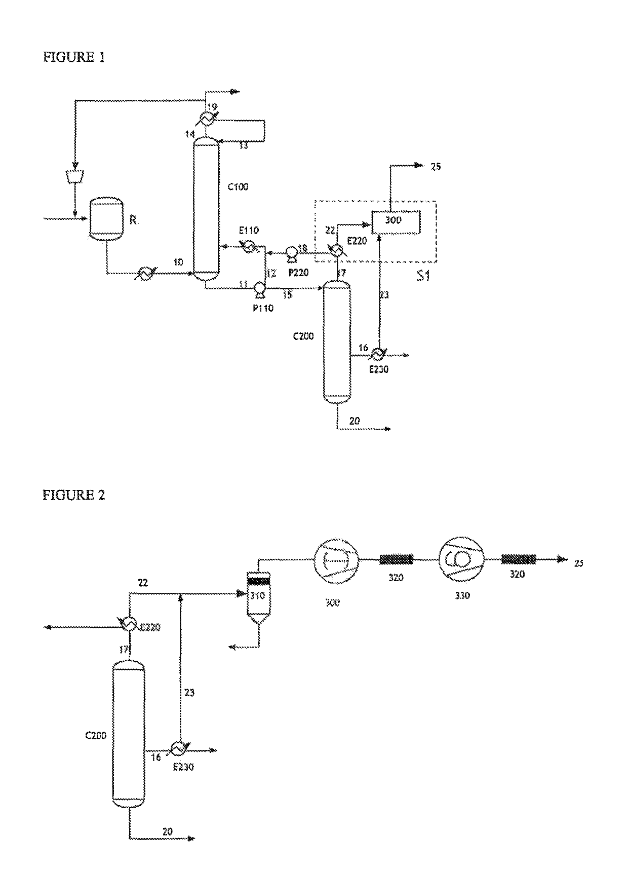
[0136]With reference to FIG. 1, in a process for the continuous production of acrylic acid from propylene, a reaction mixture 10 was subjected to the recovery / purification process according to the invention.

[0137]In this process, 11 000 kg / h of technical acrylic acid are produced (stream 16), having a purity of 99.8%. The main impurities are acetic acid (0.05%), propionic acid (0.021%), furfural (0.014%), benzaldehyde (0.008%) and maleic anhydride (0.037%).

[0138]The gaseous stream 22 (67.6 kg / h) originating from the condenser E220 at the top of the finishing column C200 was subjected to a dry vacuum pump 300. This pump provides a pressure of 12 kPa at the top of the column C200. A stream 23 (7.3 kg / h) originating from the condenser E230 placed at the side outlet of the technical acrylic acid stream was sent at the same time to the dry vacuum pump 300....

examples 2 and 3 (comparative)

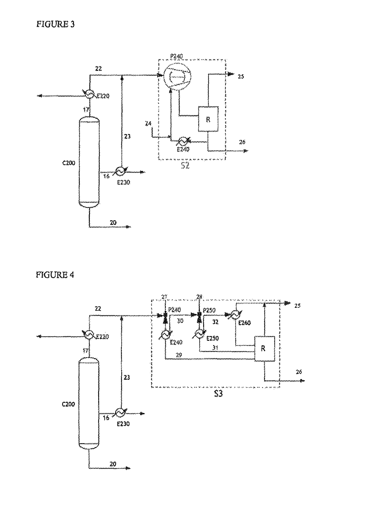
[0144]By way of comparison, the same streams 22 and 23 were subjected respectively to a liquid ring pump (Example 2, FIG. 3) as a replacement for the dry vacuum pump, and to a system incorporating steam ejectors (Example 3, FIG. 4).

[0145]In particular, Example 3 involves a steam ejector vacuum generator technology described in document U.S. Pat. No. 6,677,482 or 7,288,169.

[0146]Represented in FIG. 3 is a system S2 that incorporates a liquid ring pump P240, fed by a water stream 24. The flow rate of the stream 24 introduced into the pump in order to provide a pressure of 12 kPa is 1000 kg / h. This system S2 comprises a pump P240, an exchanger E240 and a receptacle for collecting the condensates R.

[0147]The pump P240 is fed on the one hand by the gaseous streams 22 and 23 originating from the column C200 and on the other hand by the aqueous stream 27. The main role of this aqueous stream is to constitute a liquid seal necessary for the generation of the vacuum in the pump and to ensure...

example 4

[0157]In order to avoid the expensive treatment of the aqueous stream resulting from the liquid ring pump (Example 2) or from the ejector system (Example 3), and to recover a portion of the acrylic acid contained in these streams, it may be envisaged to recycle these streams to the solvent-free purification process.

[0158]A simulation of the solvent-free purification process was carried out using ASPEN software, incorporating a recycling of the aqueous stream 26 condensed in Example 3 (ejectors in series), as a mixture with the stream 18 sent to the dehydration column C100 (see FIG. 1).

[0159]Under these conditions, contrary to the desired objective, it is observed that the recycling of this aqueous stream (1032 kg / h) gives rise to a significant loss of acrylic acid at the top of the condensation column C100.

[0160]The loss of acrylic acid in the stream 19 cooled to 61° C. is 1.74%, i.e. an acrylic acid recovery yield of 98.26%.


PUM

PropertyMeasurementUnit
weight ratioaaaaaaaaaa
pressureaaaaaaaaaa

Abstract

The invention is directed to a process for recovering / purifying (meth)acrylic acid which does not use azeotropic solvent and is based on the use of two columns for purifying a reaction mixture comprising (meth)acrylic acid. The process according to the invention includes a dry vacuum pump condensation system, which makes it possible to reduce the amount of final aqueous discharges.

Description

CROSS-REFERENCE TO RELATED APPLICATIONS[0001]This application is a national stage application under 35 U.S.C. § 371 of PCT / FR2016 / 050501, filed Mar. 4, 2016 which claims benefit to application FR15.52049, filed Mar. 12, 2015.TECHNICAL FIELD[0002]The present invention relates to the production of (meth)acrylic acid.[0003]One subject of the invention is more particularly a process for recovering / purifying (meth)acrylic acid which does not use azeotropic solvent and is based on the use of two columns for purifying a reaction mixture comprising (meth)acrylic acid. The process according to the invention includes a dry vacuum pump condensation system, which makes it possible to reduce the amount of final aqueous discharges.[0004]The invention also relates to a plant suitable for the implementation of this process.TECHNICAL BACKGROUND AND TECHNICAL PROBLEM[0005]Manufacturers have been developing processes for synthesizing acrylic acid for decades.[0006]The process which today is the most w...

Claims


Application Information

Patent Timeline
Patent Type & Authority Patents(United States)
IPC IPC(8): B01D3/10C07C51/25C07C51/44B01D5/00C07C57/04
CPCC07C51/44B01D3/10B01D5/0045C07C51/252C07C57/04C07C51/21
Inventor JAIN, SANDEEPLACROIX, CHRISTIANFAUCONET, MICHEL JEAN
Owner ARKEMA FRANCE SA
Why Eureka
Try Eureka