Engine

a technology of engine and engine body, applied in the field of engines, can solve problems such as reducing chances, and achieve the effect of improving maintenance efficiency

Active Publication Date: 2019-03-26
YAMAHA MOTOR POWER PROD KK
View PDF20 Cites 2 Cited by
  • Summary
  • Abstract
  • Description
  • Claims
  • Application Information

AI Technical Summary

Benefits of technology

[0006]Preferred embodiments of the present invention provide an engine which is able to improve maintenance efficiency.
[0008]According to a preferred embodiment of the present invention, by only removing the second cover, it is possible to use the first opening and the second opening in the first cover to remove debris such as turf grass and other plants easily from areas of the cooling fan and the fins of the cylinder, thus improving the efficiency of performing maintenance.
[0009]Preferably, the first cover further includes a wall between the first opening and the second opening. In this case, the wall decreases chances for debris such as turf grass and other plants to enter from the air inlet into the second opening.
[0010]Further preferably, the wall is located at an edge region of the second opening. In this case, the wall further decrease chances for debris such as turf grass and other plants to enter from the air inlet into the second opening.

Problems solved by technology

In this case, the wall decreases chances for debris such as turf grass and other plants to enter from the air inlet into the second opening.

Method used


Image

  • Engine
  • Engine
  • Engine

Examples


Embodiment Construction

[0027]Hereinafter, preferred embodiments of the present invention will be described with reference to the drawings.

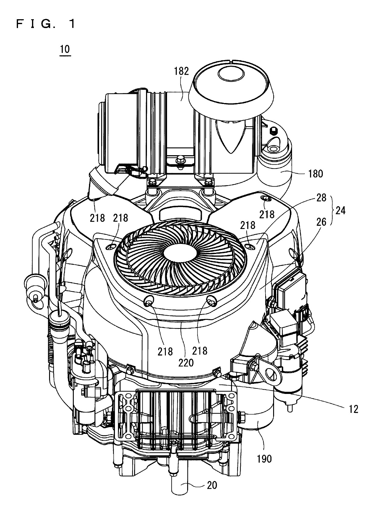
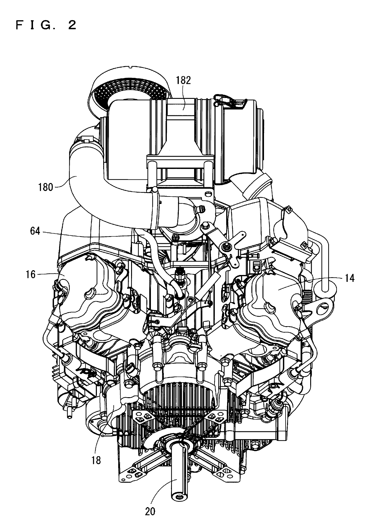
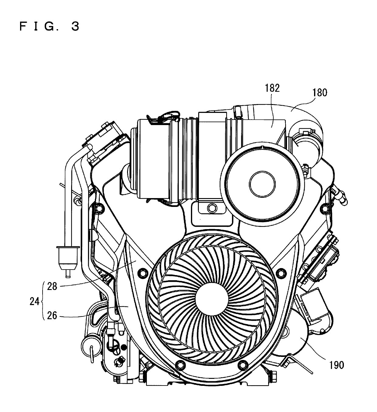
[0028]Referring to FIG. 1 through FIG. 6, an engine 10 according to a preferred embodiment of the present invention is, for example, a vertical, narrow-angle (less than 90 degrees), V-shaped, two-cylinder, OHV engine (Over Head Valve Engine). The engine 10 includes a crankcase 12. Two cylinders 14, 16 are arranged in a V-shape on a side surface of the crankcase 12. An oil pan 18 is provided below the crankcase 12. A crank shaft 20 is arranged inside the crankcase 12 and the oil pan 18 so that its axial direction extends in an up-down direction (see FIG. 7). The crank shaft 20 penetrates the crankcase 12 and the oil pan 18 in the up-down direction. Referring to FIG. 7, above the crankcase 12, a cooling fan 22 is arranged coaxially with the crank shaft 20. The cooling fan 22 is driven by the crank shaft 20, and introduces cooling air from above the crankcase 12. A cover p...


PUM


Abstract

An engine includes a crankcase with cylinders and fins on outer circumferences of the cylinders. A crank shaft penetrates the crankcase. A cooling fan is provided on an outer side of the crankcase and arranged coaxially with the crank shaft. A first cover covers an outer side of the cylinders and the crankcase, and the cooling fan. A second cover capable of being detached from / attached to the first cover. The first cover includes a first opening facing the cooling fan, and second openings facing the fins. The second cover includes an air inlet facing the first opening, and attached to the first cover to cover the first opening and the second openings.

Description

BACKGROUND OF THE INVENTION[0001]1. Field of the Invention[0002]The present invention relates to engines, and more specifically to an engine used in machinery such as mowing equipment.[0003]2. Description of the Related Art[0004]JP-A H10-169445 discloses an example of an engine of the above type. JP-A H10-169445 discloses an air-cooled engine wherein an engine main body supports a crank shaft, at an end of which, a cooling fan is attached. An air inlet faces a front surface of the cooling fan, and in order to introduce cooling air sucked from the air inlet to a cylinder block of the engine main body, there is provided a shroud which covers a side of the engine main body, and a screen grid which covers the air inlet and is fixed to the cooling fan.[0005]The engine disclosed in JP-A H10-169445 requires time-consuming removal of the shroud itself at times of maintenance activities such as cleaning the vicinity of fins which are provided on an outer circumference of the cylinder block, ...

Claims


Application Information

Patent Timeline
Patent Type & Authority Patents(United States)
IPC IPC(8): F02P1/02F01P1/06F01P5/02F02F1/06F01P5/06F01P1/02F02F7/00
CPCF01P1/02F01P1/06F01P5/02F02F1/06F02F7/007F01P5/06F01P2001/026F01P2001/023
Inventor NISHI, KENGOJINNOHARA, NOBUOTSUDA, SHINYA
Owner YAMAHA MOTOR POWER PROD KK
Why Eureka
Try Eureka