Surgical stapler with circumferential firing

a technology of circumferential firing and stapler, which is applied in the field of surgical staplers, can solve the problems of inherent limitation of staple leg length, and achieve the effect of novel jaw reinforcement structures and small diameter

Active Publication Date: 2019-04-02
APPL MEDICAL RESOURCES CORP
View PDF41 Cites 723 Cited by
  • Summary
  • Abstract
  • Description
  • Claims
  • Application Information

AI Technical Summary

Benefits of technology

[0012]A surgical stapler is provided. The stapler employs circumferential channels through which staples are deployed along an arc pathway against an anvil surface. The curved channels allow staples with relatively longer legs to be used in the stapler of the present invention having a smaller diameter at the jaws. Also, by utilizing a curved path, a much larger staple can be placed in the same diameter device. In certain embodiments, a staple up to three times larger can be employed in a stapler of the present invention. Specialized curved staples for use with the stapler of the present invention are also provided. To further enable the benefits of the stapler with circumferential staple channels and method of staple deployment, novel jaw reinforcement structures are also provided in the present invention. The stapler jaw reinforcement structures are located towards the center or bladeline of the device instead of around the circumference as in conventional staplers, thereby clearing the outer area near the circumference of the device to provide room for longer staples and staple firing components.

Problems solved by technology

This is an inherent limitation of staple leg length in smaller diameter staplers employing the same conventional design.

Method used


Image

  • Surgical stapler with circumferential firing
  • Surgical stapler with circumferential firing
  • Surgical stapler with circumferential firing

Examples


Embodiment Construction

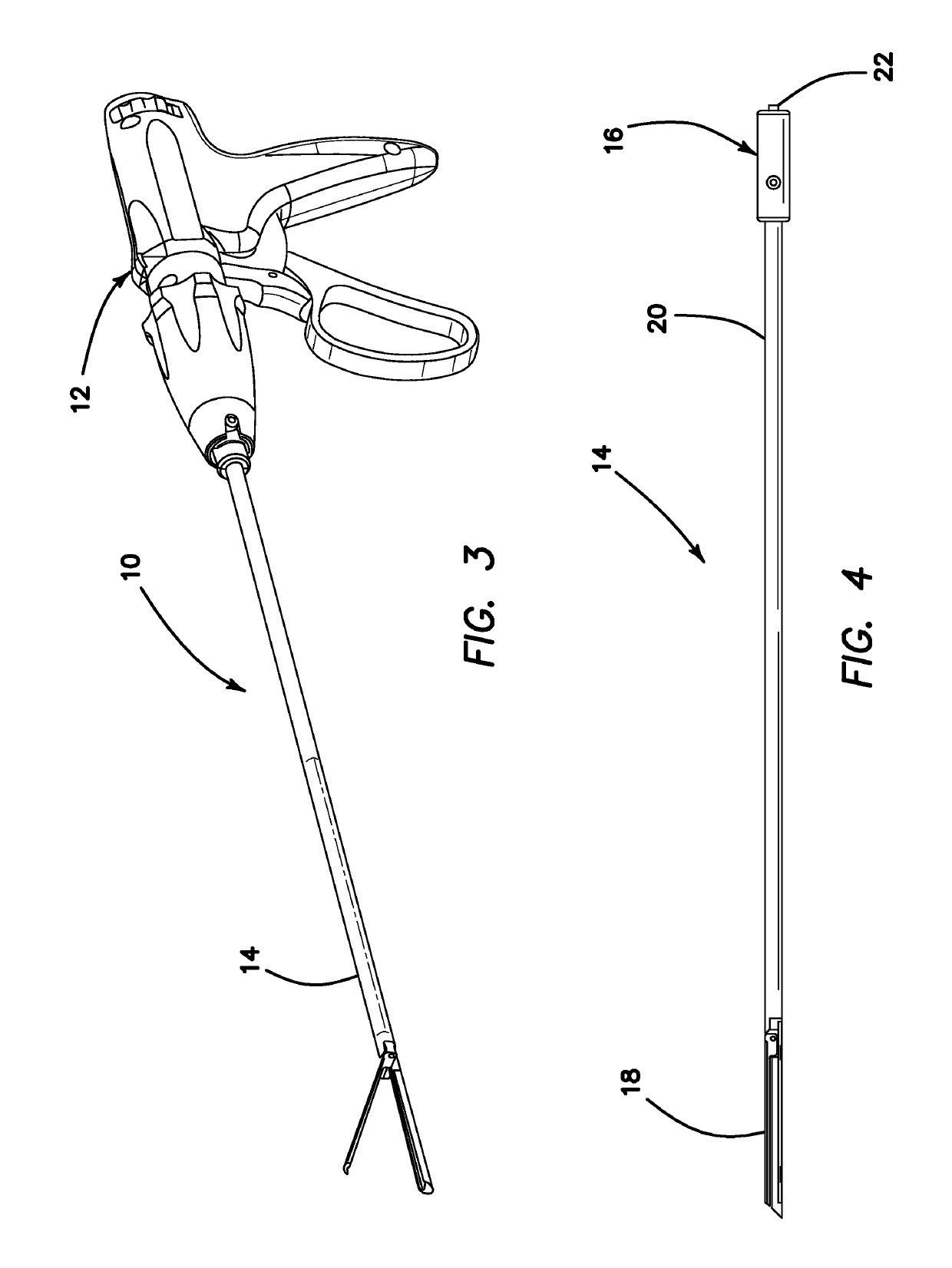
[0120]Referring to FIG. 3, there is shown a perspective view of a surgical stapler 10 according to the present invention. The stapler 10 is comprised of a handle assembly 12 removably connected to a stapler cartridge assembly 14. The handle assembly 12 is configured to control the instrument and actuate the deployment of staples located in the distal end of the stapler cartridge assembly 14. After the staples have been expended from the stapler 10, the stapler cartridge assembly 14 is removed from the handle assembly 12 and a new stapler cartridge assembly 14 is connected to the handle assembly 12 for continued stapling. In an alternative variation, a separate staple cartridge is replaceable from the distal end of the stapler cartridge assembly 14 for continued stapling.

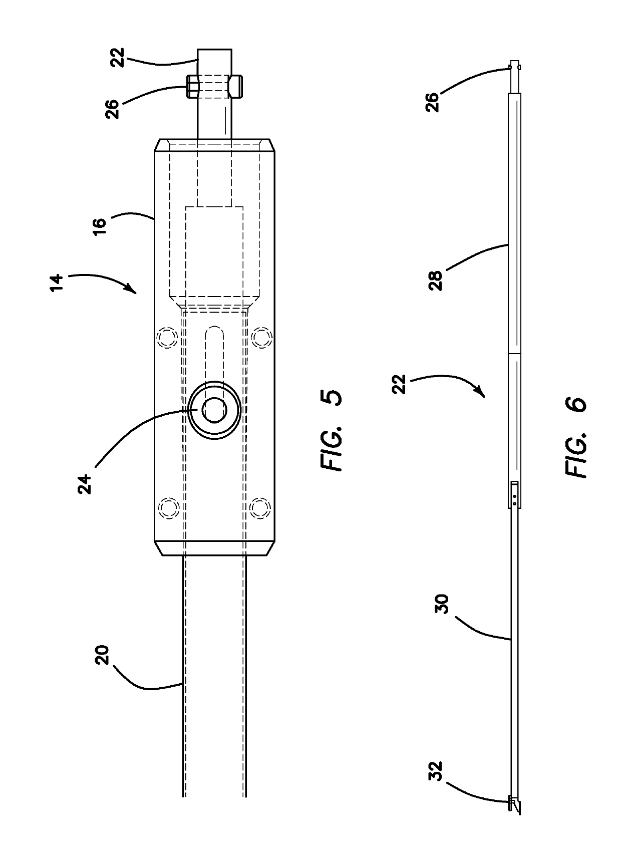
[0121]Turning to FIG. 4, the stapler cartridge assembly 14 will now be discussed in detail. The stapler cartridge assembly 14 includes a connector 16 at the proximal end and an end effector 18 at the distal end. An o...


PUM


Abstract

A surgical stapler is provided. The stapler employs circumferential channels through which staples are deployed along an arc pathway against an anvil surface. The curved channels allow staples with relatively longer legs to be used in the stapler having a smaller diameter at the jaws. Also, by utilizing a curved path, a much larger staple can be placed in the same diameter device. Specialized curved staples for use with the stapler of the present invention are also provided. To further enable the benefits of the stapler with circumferential channels and method of staple deployment, novel jaw reinforcement structures are provided in the present invention. The jaw reinforcement structures are located towards the center or bladeline of the device instead of around the circumference as in conventional staplers, thereby clearing the outer area near the circumference of the device to provide room for longer staples and staple firing components.

Description

CROSS-REFERENCE TO RELATED APPLICATION[0001]This application is a continuation of International Application No. PCT / US2015 / 035379 entitled “Surgical stapler with circumferential firing” filed on Jun. 11, 2015 and hereby incorporated herein by reference in its entirety, which claims priority to and benefit of U.S. Provisional Patent Application Ser. No. 62 / 010,883 entitled “Surgical stapler with circumferential firing” filed on Jun. 11, 2014 which is hereby incorporated herein by reference in its entirety.FIELD OF THE INVENTION[0002]This disclosure relates to surgical instruments, and more particularly, to surgical stapling instruments for applying a plurality of surgical staples to body tissue.BACKGROUND OF THE INVENTION[0003]A typical surgical stapler apparatus comprises a handle at a proximal end and two elongated jaw-like members at the distal end, joined together at a hinge. The jaw-like members articulate to open and close to capture tissue between the jaw-like members. The use...

Claims


Application Information

Patent Timeline
Patent Type & Authority Patents(United States)
IPC IPC(8): A61B17/10A61B17/064A61B17/072
CPCA61B17/105A61B17/0644A61B17/07207A61B2017/07278A61B2017/0641A61B2017/07271A61B2017/0046A61B2017/07285A61B2017/07221A61B2017/07264
Inventor HOPKINS, TIMOTHY M.PATEL, ATAL C.GADBERRY, DONALD L.BECERRA, MATTHEW M.
Owner APPL MEDICAL RESOURCES CORP
Why Eureka
Try Eureka