Pneumatic tire having lug grooves forming a direction tread pattern

a technology of lug grooves and pneumatic tires, which is applied in the direction of inflatable tires, vehicle components, transportation and packaging, etc., can solve the problems of poor steering stability performance, wear resistance drop in steering stability performance on dry road surfaces, so as to improve steering stability performance, and increase the number of grooves

Inactive Publication Date: 2019-04-02
BRIDGESTONE CORP
View PDF24 Cites 0 Cited by
  • Summary
  • Abstract
  • Description
  • Claims
  • Application Information

AI Technical Summary

Benefits of technology

[0005]To improve the steering stability performance on dry road surfaces, it is necessary to make the ground contact area larger to secure the block rigidity. On the other hand, to improve the steering stability performance on wet road surfaces, it is necessary to increase the number of grooves and raise the drainage (dewatering) performance.
[0007]Also, the so-called round ground contact shape is advantageous in improving the steering stability performance on wet road surfaces. However, the tires having such a ground contact shape tend generally to show inferior steering stability performance and wear resistance performance on dry road surfaces.
[0008]The present invention has been made in view of these conventional problems, and an object thereof is to provide a pneumatic tire that can not only ensure the steering stability performance on wet road surfaces, but also improve the steering stability performance and wear resistance performance on dry road surfaces.Means for Solving the Problem

Problems solved by technology

That is, an attempt at improving the steering stability performance on wet road surfaces may result in a drop in the steering stability performance on dry road surfaces.
However, the tires having such a ground contact shape tend generally to show inferior steering stability performance and wear resistance performance on dry road surfaces.

Method used


Image

  • Pneumatic tire having lug grooves forming a direction tread pattern
  • Pneumatic tire having lug grooves forming a direction tread pattern
  • Pneumatic tire having lug grooves forming a direction tread pattern

Examples


first embodiment

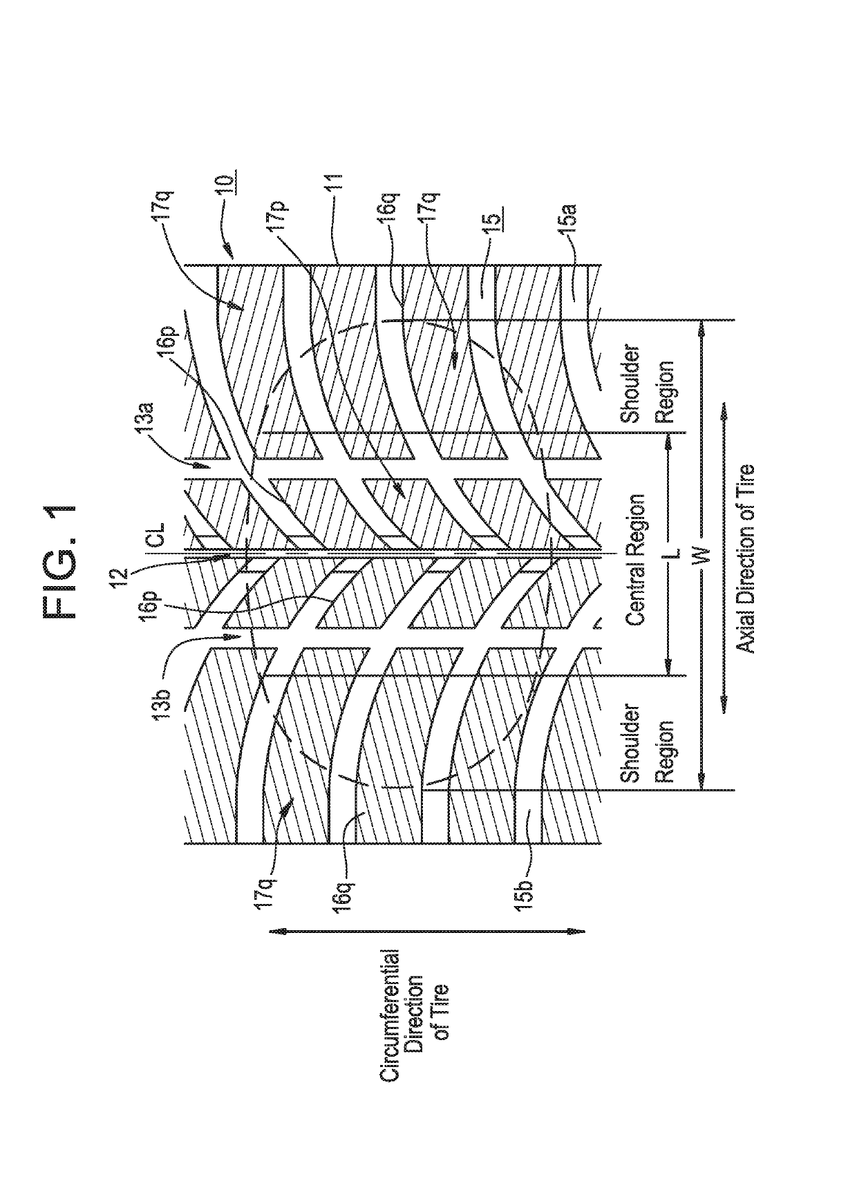
[0032]FIG. 1 is an illustration showing an example of a tread pattern of a tread 11 of a pneumatic tire (hereinafter referred to as a tire) 10 according to a first embodiment of the present invention. The vertical direction of the illustration is the circumferential direction of the tire, and the horizontal direction the axial direction of the tire.

[0033]The tire 10 has at least one layer of carcass toroidally straddling between a pair of beads as the framework. At least one layer of a belt layer is disposed radially outside of the crown part of the carcass. And a tread pattern as shown in FIG. 1 is formed in a surface of tread rubber which is disposed radially outside of the belt layer.

[0034]Hereinafter, the region enclosed by two straight parallel lines each passing through the center between the straight line (CL: center line) passing through the contact width center and the contact edge of the contact patch of the tire indicated by a thick broken line in FIG. 1 will be referred ...

second embodiment

[0058]FIG. 1 is an illustration showing a pneumatic tire (hereinafter referred to as a tire) 10Z according to a second embodiment of the present invention. And the outline of the ground contact shape of the tire 10Z is delineated by a thick solid line in the figure.

[0059]The tread pattern of the tire 10Z is the same as that of the tire 10 shown in FIG. 1, with three circumferentially continuous circumferential grooves (circumferential grooves 12, 13a, 13b) formed in the central region and V-shaped lug grooves 15.

[0060]Hereinafter, of the blocks 16, the blocks 16p defined by the circumferential groove 12 located in the center, the circumferential groove 13a (or circumferential groove 13b), and the lug grooves 15 will be referred to as the inner blocks, and the blocks 16q defined by the circumferential groove 13a (or circumferential groove 13b) located outside and the lug grooves 15 will be referred to as the outer blocks.

[0061]The tire 10Z of this embodiment has a ground contact shap...

third embodiment

[0081]FIG. 8 is an illustration showing an example of a tread pattern of a tread 11 of a pneumatic tire (hereinafter referred to as a tire) 10A according to this embodiment of the present invention.

[0082]Formed in the surface of the tread 11 are a central circumferential groove 12, intermediate circumferential grooves 13a, 13b, shoulder grooves 14a, 14b, and lug grooves 15. The central circumferential groove 12 and the intermediate circumferential grooves 13a, 13b are circumferential grooves disposed in the central region and extending continuously along the circumference of the tire. In the present embodiment, the groove width of the intermediate circumferential grooves 13a, 13b is set wider than the width of the central circumferential groove 12.

[0083]The shoulder grooves 14a, 14b are circumferential grooves provided axially outside of the intermediate circumferential grooves 13a and 13b respectively and extending discontinuously in their approximately circumferential directions. ...


PUM


Abstract

A pneumatic tire (10), which has, in the surface of the tread (11), lug grooves (15) on one side extending from one axial edge towards the axial center of the tire in such a manner as to intersect with the circumferential direction of the tire and lug grooves (15) on the other side extending in a symmetrically opposite direction from the axial center towards the other axial edge of the tire, has at least one circumferential groove (12) extending circumferentially around the tire. Also, circumferential grooves (12, 13a, 13b) are so formed as to satisfy a relationship of “1≤(S / L)≤3” where L is the axial length of the central region, which is the region enclosed by two straight parallel lines each passing through the center between the contact width center (CL) and the contact edge with the shoulder regions being the regions axially outside of the parallel lines, and S is the total of the groove areas of the circumferential grooves (12, 13a, 13b) disposed in the central region. Therefore, the pneumatic tire (10) not only secures the steering stability performance on wet road surfaces, but also improves the steering stability and wear resistance performance on dry road surfaces.

Description

CROSS REFERENCE TO RELATED APPLICATIONS[0001]This application is a National Stage of International Application No. PCT / JP2013 / 082099 filed Nov. 28, 2013, claiming priority based on Japanese Patent Application No. 2012-263816, filed Nov. 30, 2012, the contents of all of which are incorporated herein by reference in their entirety.TECHNICAL FIELD[0002]The present invention relates to a pneumatic tire having circumferential grooves and lug grooves formed in the tread surface and, more particularly, to a pneumatic tire which excels in steering stability.BACKGROUND ART[0003]Conventionally, attempts have been made to improve the steering stability performance of tires by providing, in the tread surface, circumferential grooves extending circumferentially around the tire and lug grooves extending in such a manner as to intersect with the circumferential direction, which ensures the braking performance by the edge effect of the blocks (see Patent Document 1, for instance).CONVENTIONAL ARTPa...

Claims


Application Information

Patent Timeline
Patent Type & Authority Patents(United States)
IPC IPC(8): B60C11/03B60C5/00B60C11/12B60C11/13
CPCB60C11/0311B60C11/0302B60C11/033B60C11/0306B60C11/0332B60C11/1236B60C11/1263B60C11/1369B60C5/00B60C2011/1209B60C2011/0313B60C2011/0341B60C2011/0344B60C2011/0369B60C2011/0374
Inventor KATAYAMA, SHINSAKUSETA, EISUKEKAJI, YOSHIOKOIDE, MASAFUMIKURATA, TAKAYUKIKATSUNO, HIROYUKIAMANO, MASAKAZUTAKEI, ATAKA
Owner BRIDGESTONE CORP
Why Eureka
Try Eureka