Torque reaction frame for mitigation of rear impact effects

a rear impact and torque reaction technology, applied in the field of vehicle chassis components, can solve problems such as contact between the rear-mounted components of the vehicle and other rear-mounted components, and achieve the effect of reducing or preventing damag

Inactive Publication Date: 2019-04-02
GM GLOBAL TECH OPERATIONS LLC
View PDF17 Cites 4 Cited by
  • Summary
  • Abstract
  • Description
  • Claims
  • Application Information

AI Technical Summary

Benefits of technology

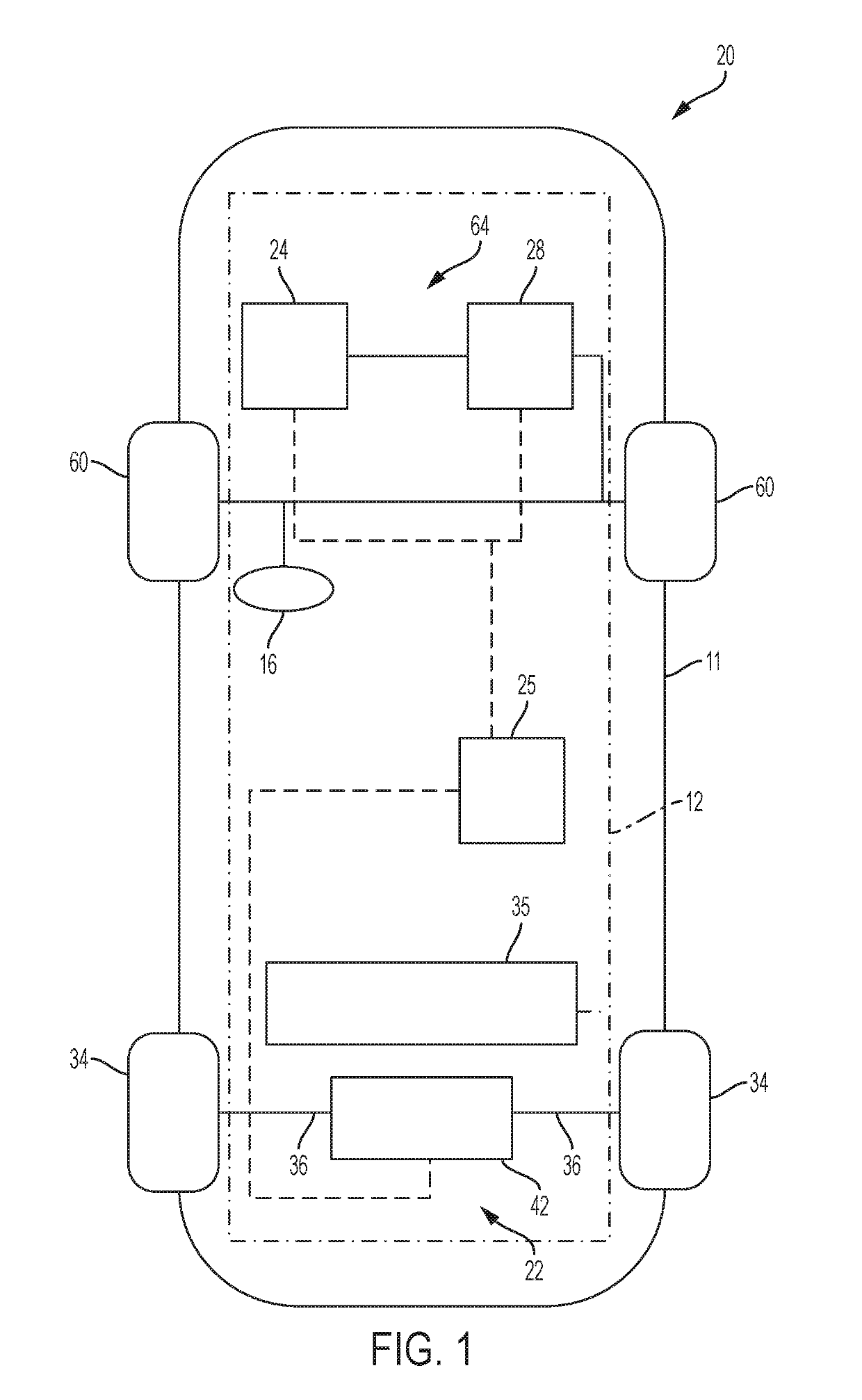
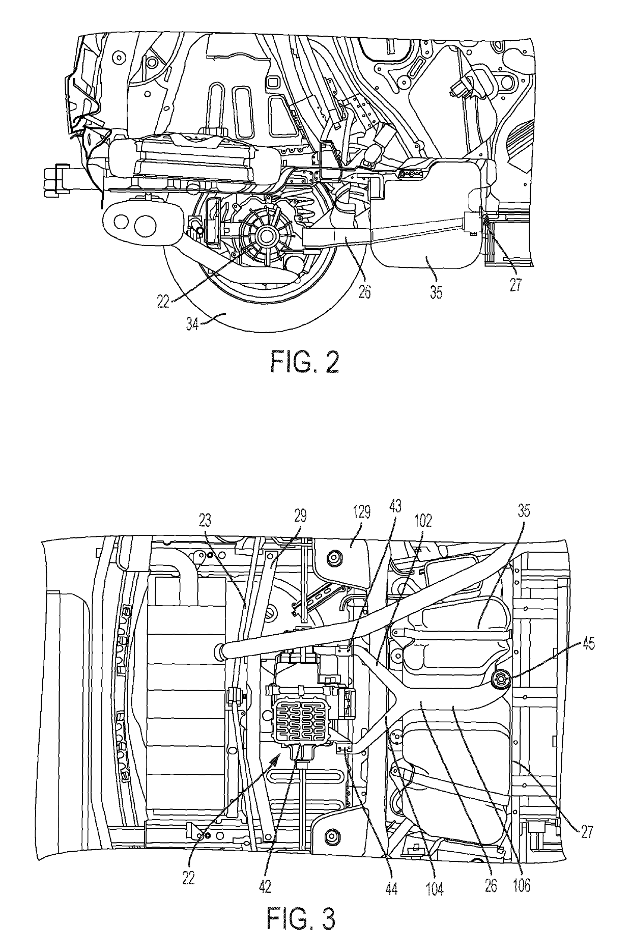
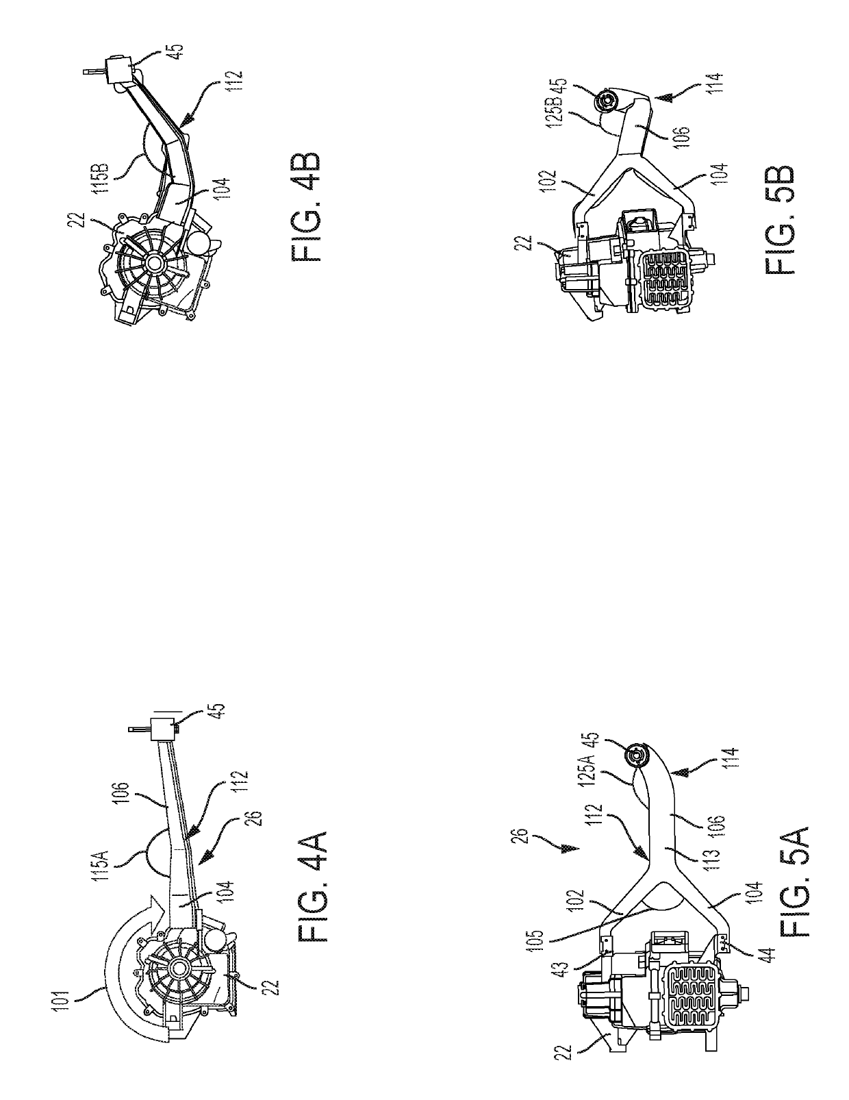
[0003]Embodiments according to the present disclosure provide a number of advantages. For example, embodiments of the structural chassis components according to the present disclosure reduce or prevent damage to rear-mounted components, such as a fuel tank, fuel cell, and / or a battery module, due to contact from the eRDM.
[0010]In some aspects, the automotive vehicle further includes a storage component, wherein the bolted connection is forward of the storage component such that deformation of the frame prevents a collision between the rear drive module and the storage component.

Problems solved by technology

When a vehicle is subject to a rear impact, movement of the eRDM due to the impact forces can cause harsh contact between the eRDM and other rear-mounted components of the vehicle, including the fuel tank, fuel cell, and / or battery pack.

Method used


Image

  • Torque reaction frame for mitigation of rear impact effects
  • Torque reaction frame for mitigation of rear impact effects
  • Torque reaction frame for mitigation of rear impact effects

Examples


Embodiment Construction

[0023]Embodiments of the present disclosure are described herein. It is to be understood, however, that the disclosed embodiments are merely examples and other embodiments can take various and alternative forms. The figures are not necessarily to scale; some features could be exaggerated or minimized to show details of particular components. Therefore, specific structural and functional details disclosed herein are not to be interpreted as limiting, but merely as a representative basis for teaching one skilled in the art to variously employ the present invention. As those of ordinary skill in the art will understand, various features illustrated and described with reference to any one of the figures can be combined with features illustrated in one or more other figures to produce embodiments that are not explicitly illustrated or described. The combinations of features illustrated provide representative embodiments for typical applications. Various combinations and modifications of ...


PUM


Abstract

A device for rear impact mitigation of a vehicle is disclosed herein. In some embodiments, the device includes a Y-shaped frame having a first leg, a second leg, and a reaction member, the reaction member having a first end and a second end, the first leg and the second leg extending from the first end of the reaction member at a first area and defining an angle therebetween, the reaction member having a straight portion proximate the first end and a curved portion defining a second area proximate the second end, wherein the frame is configured to deform at one or more of the first area and the second area upon application of a force from a rear impact event to the vehicle.

Description

INTRODUCTION[0001]The present invention relates generally to the field of vehicles and, more specifically, to structural chassis components that mitigate the effects of a rear impact crash.[0002]Electric vehicles include an electric rear drive module (eRDM) as part of or as the sole source of vehicle propulsion. The eRDM receives signals from a controller and electricity from a power source to convert electrical energy into rotational energy that is transmitted to the rear wheels of the vehicle. When a vehicle is subject to a rear impact, movement of the eRDM due to the impact forces can cause harsh contact between the eRDM and other rear-mounted components of the vehicle, including the fuel tank, fuel cell, and / or battery pack. Accordingly, it is desirable to provide a system for reducing or preventing damage to these and other components due to impact forces from a rear impact event.SUMMARY[0003]Embodiments according to the present disclosure provide a number of advantages. For ex...

Claims


Application Information

Patent Timeline
Patent Type & Authority Patents(United States)
IPC IPC(8): B62D21/15B60K1/00
CPCB60K1/00B62D21/152B62D21/155B60K2001/001B60Y2306/01
Inventor LEIER, BRADLEYSTIBICH, ANNE M.BABURAJAN, BHARATH KUMAR
Owner GM GLOBAL TECH OPERATIONS LLC
Why Eureka
Try Eureka