Means for alleviating strain on a wind turbine rotor blade
a technology for wind turbines and rotor blades, applied in the field of rotor blades, can solve the problems of actuation and control systems, airplanes have the drawbacks of relatively high cost, high durability requirements, and difficulty in accessing the system for servicing, and achieve the effect of alleviating the load on the rotor blades
- Summary
- Abstract
- Description
- Claims
- Application Information
AI Technical Summary
Benefits of technology
Problems solved by technology
Method used
Image
Examples
first embodiment
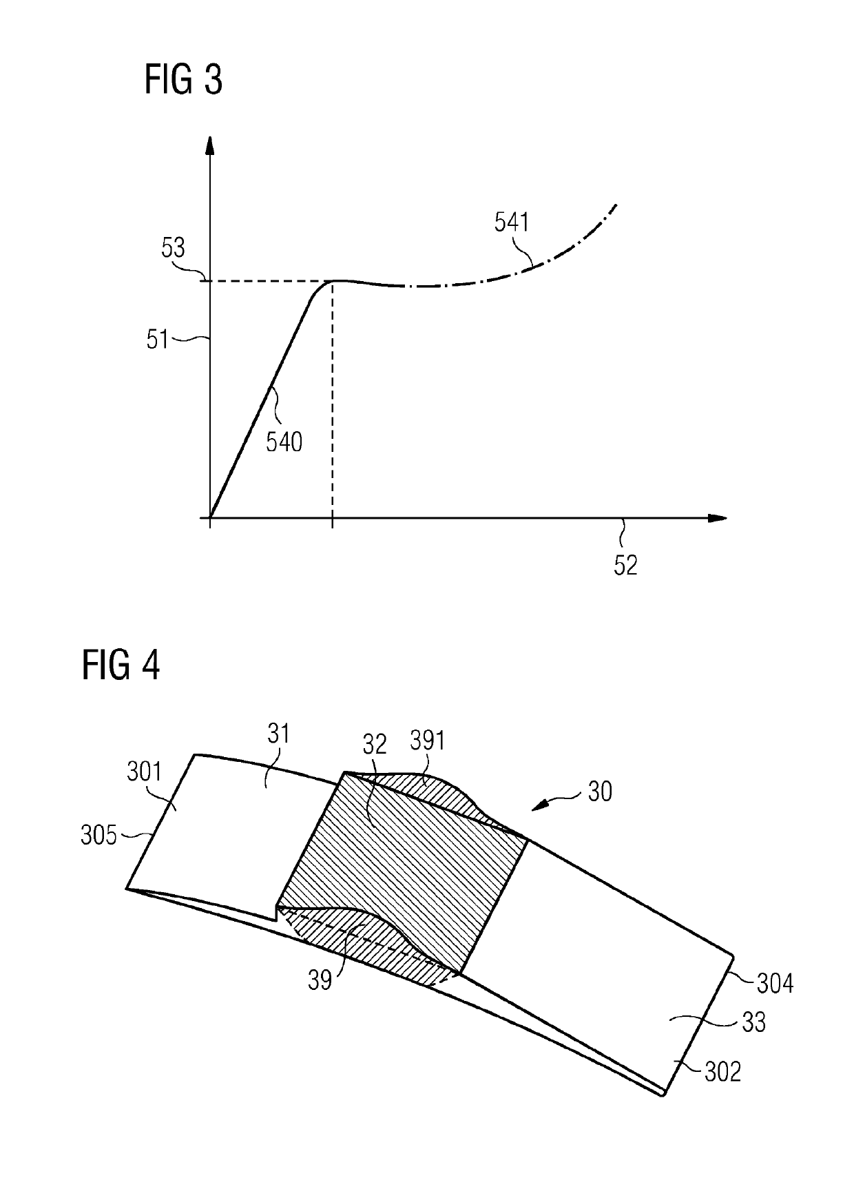
[0114]The first embodiment is shaped as in a U-shape. In other words, it comprises a plane and two stabilizers, namely a stabilizer 39 and a further stabilizer 391, the two stabilizers 39, 391 being arranged perpendicularly to the plane.
[0115]In can be seen in FIG. 6 that, if a force is applied in flapwise direction on the aerodynamic device, a bending moment 55 results, and the aerodynamic device 30 deforms. Deformation of the aerodynamic device 30 takes place at both the planar section and the stabilizers 39, 391. As a result, the aerodynamic device 30 is bent upwards and will thus influence the aerodynamic properties of the rotor blade in the desired manner. In particular, lift of the rotor blade may be reduced. Note that the deformation is reversible and that it occurs completely passively.
second embodiment
[0116]FIGS. 7 and 8 show the invention. They show another aerodynamic device 30 with an attachment section 31 comprising a device leading edge section 301, and a buckling section 32 and an aerodynamic section 33. The aerodynamic section 33 comprises a device trailing edge section 302 and comprises a plurality of serrations 38. The purpose of the serrations 38 is mainly the reduction of noise that is generated during rotation of the rotor blade about the rotor axis of rotation.
[0117]In the example of FIG. 7, the aerodynamic device is arranged and prepared for being attached at the pressure side of a main body of a rotor blade at the trailing edge section. Furthermore, it is arranged and prepared that a force component 51 is acting on the aerodynamic device 30 such that if the force component 51 reaches the stability limit of the buckling section 32, the aerodynamic section 33 and also, at least partly, the buckling section 32 bend upwards towards the suction side of the rotor blade d...
third embodiment
[0119]FIGS. 10 and 11 show an aerodynamic device 30 comprising an attachment section 31, a buckling section 32 and an aerodynamic section 33. Again, the aerodynamic section 33 comprises a plurality of serrations 38 for reducing noise that is generated by the rotor blade of the wind turbine. Also similarly to the embodiment as shown in FIGS. 7 to 9, the aerodynamic device 30 comprises a stabilizer 39 and a further stabilizer 391 for reducing the deformation of the aerodynamic device 30 in substantially flapwise direction for forces being smaller than the stability limit of the buckling section 32. In the embodiment as shown in FIG. 10, the buckling element 32 comprises a corrugation 37. Thus, a corrugated hinge element is obtained. This has the advantage that deformation of the buckling element 32 is facilitated as can be seen in FIG. 11. This has the effect that contrary to the previous embodiment as shown in FIGS. 7 to 9, where the stabilizer 39 is bent and twisted upon deformation...
PUM
 Abstract
Description
Claims
Application Information
 - R&D
- Intellectual Property
- Life Sciences
- Materials
- Tech Scout
- Unparalleled Data Quality
- Higher Quality Content
- 60% Fewer Hallucinations
Browse by: Latest US Patents, China's latest patents, Technical Efficacy Thesaurus, Application Domain, Technology Topic, Popular Technical Reports.
© 2025 PatSnap. All rights reserved.Legal|Privacy policy|Modern Slavery Act Transparency Statement|Sitemap|About US| Contact US: help@patsnap.com


