Composite over wrap

a technology of composite materials and over-wrapping, which is applied in the direction of synthetic resin layered products, tubular articles, vehicle components, etc., can solve the problems of early shaft failure and the inability of conventional quill shafts to match the frequency resistance needed

Active Publication Date: 2019-04-02
SIKORSKY AIRCRAFT CORP
View PDF11 Cites 1 Cited by
  • Summary
  • Abstract
  • Description
  • Claims
  • Application Information

AI Technical Summary

Benefits of technology

[0006]According to one aspect of the disclosure, a composite wrap is provided for damping vibration in an elongated quill shaft having a cylindrical body. The composite wrap includes interior layering for disposition about a cylindrical body, exterior layering configured to define an exterior composite wrap shape and sequential cured-in-place, vibration damping, fibrous epoxy layers. The sequential cured-in-place, vibration damping, fibrous epoxy layers are radially interposed between the interior and exterior layering to dampen vibrations of and / or to adjust a resonance frequency of the cylindrical body.
[0012]According to another aspect of the disclosure, a quill shaft is provided and includes an elongate shaft member having a central portion and first and second opposite longitudinal ends and a composite wrap. The composite wrap includes interior layering for disposition about the central portion, exterior layering configured to define an exterior composite wrap shape and sequential cured-in-place, vibration damping, fibrous epoxy layers radially interposed between the interior and exterior layering to dampen quill shaft vibrations and / or to adjust a quill shaft resonance frequency.

Problems solved by technology

During operational conditions, excitations loads are applied to the quill shaft(s) by the various aircraft drive systems and it has been seen that dynamic natural frequency responses on certain engineered quill shafts contributed to early shaft failures.
Indeed, conventional quill shafts were often unable to match needed frequency resistance without heavyweight alternative designs.

Method used


Image

  • Composite over wrap
  • Composite over wrap
  • Composite over wrap

Examples


Embodiment Construction

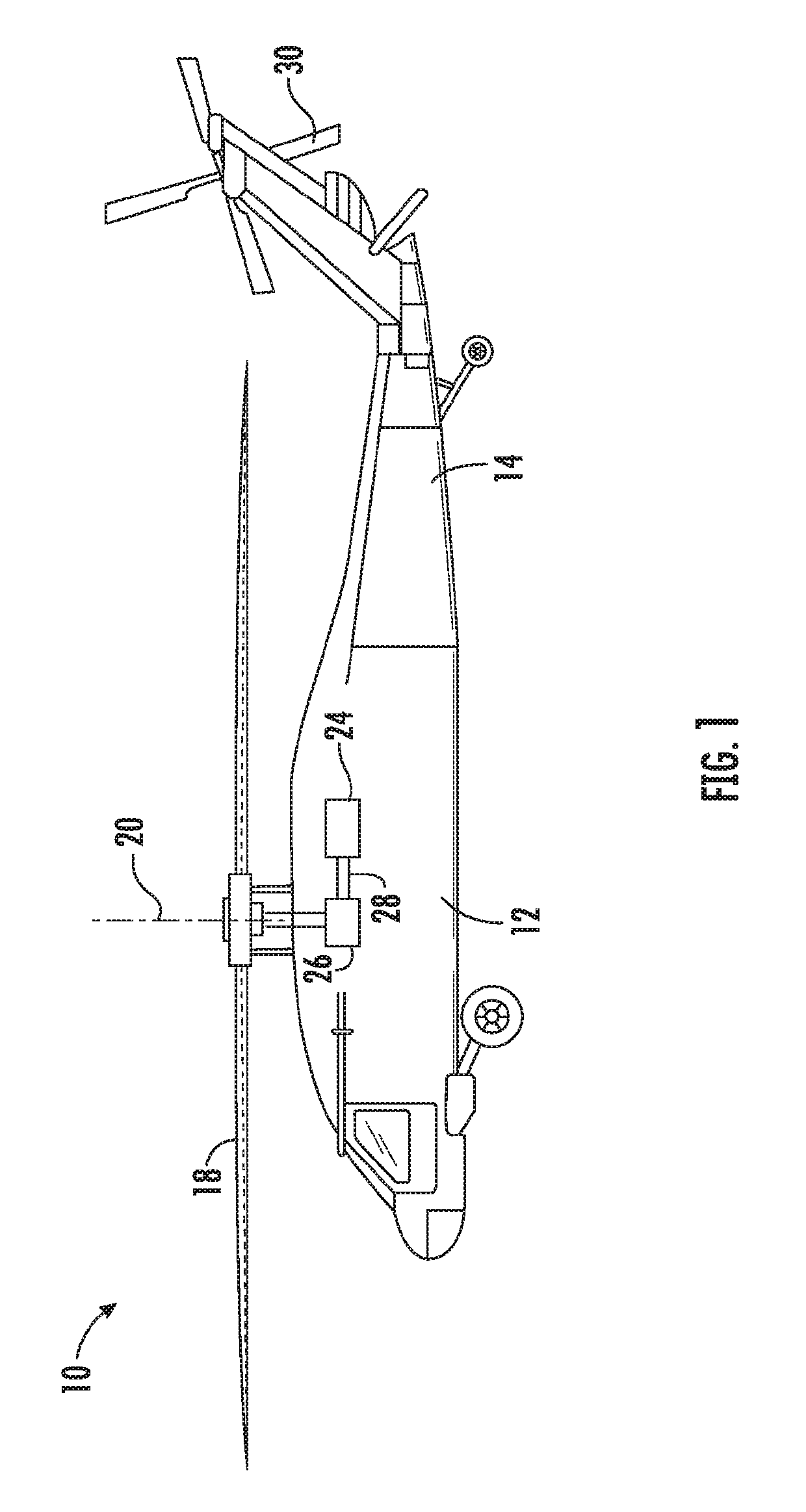
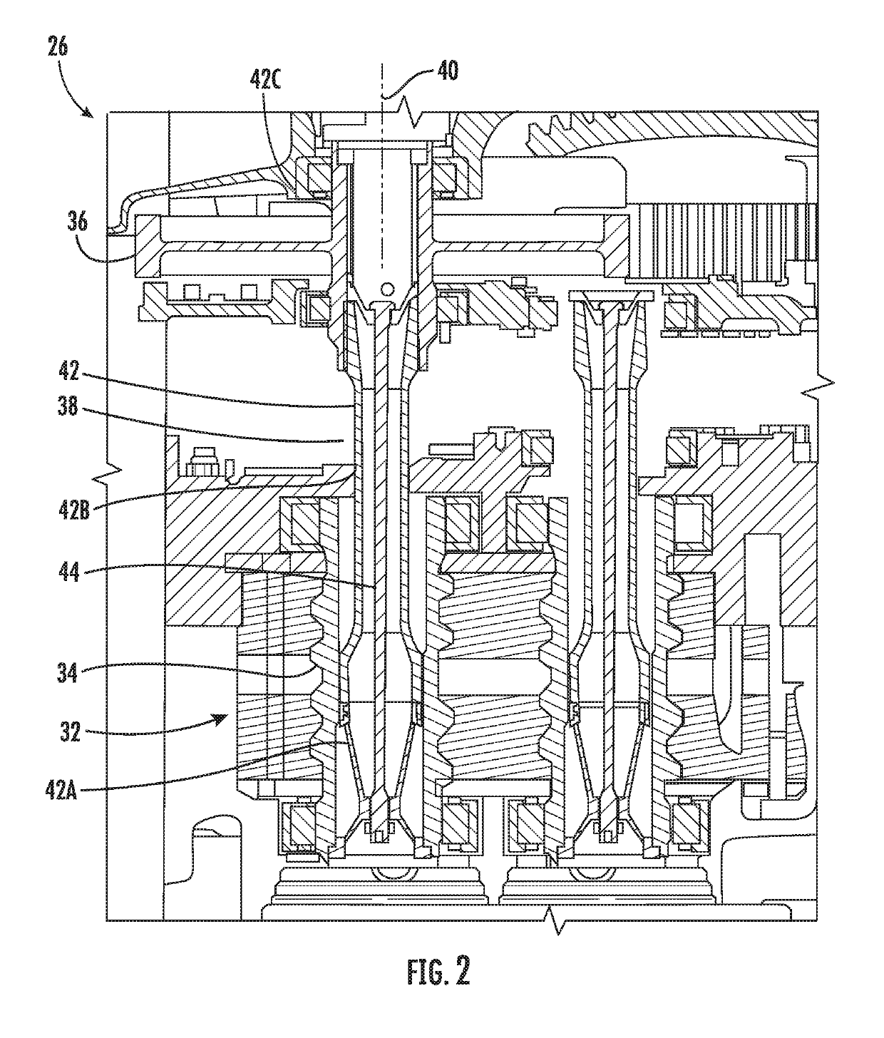
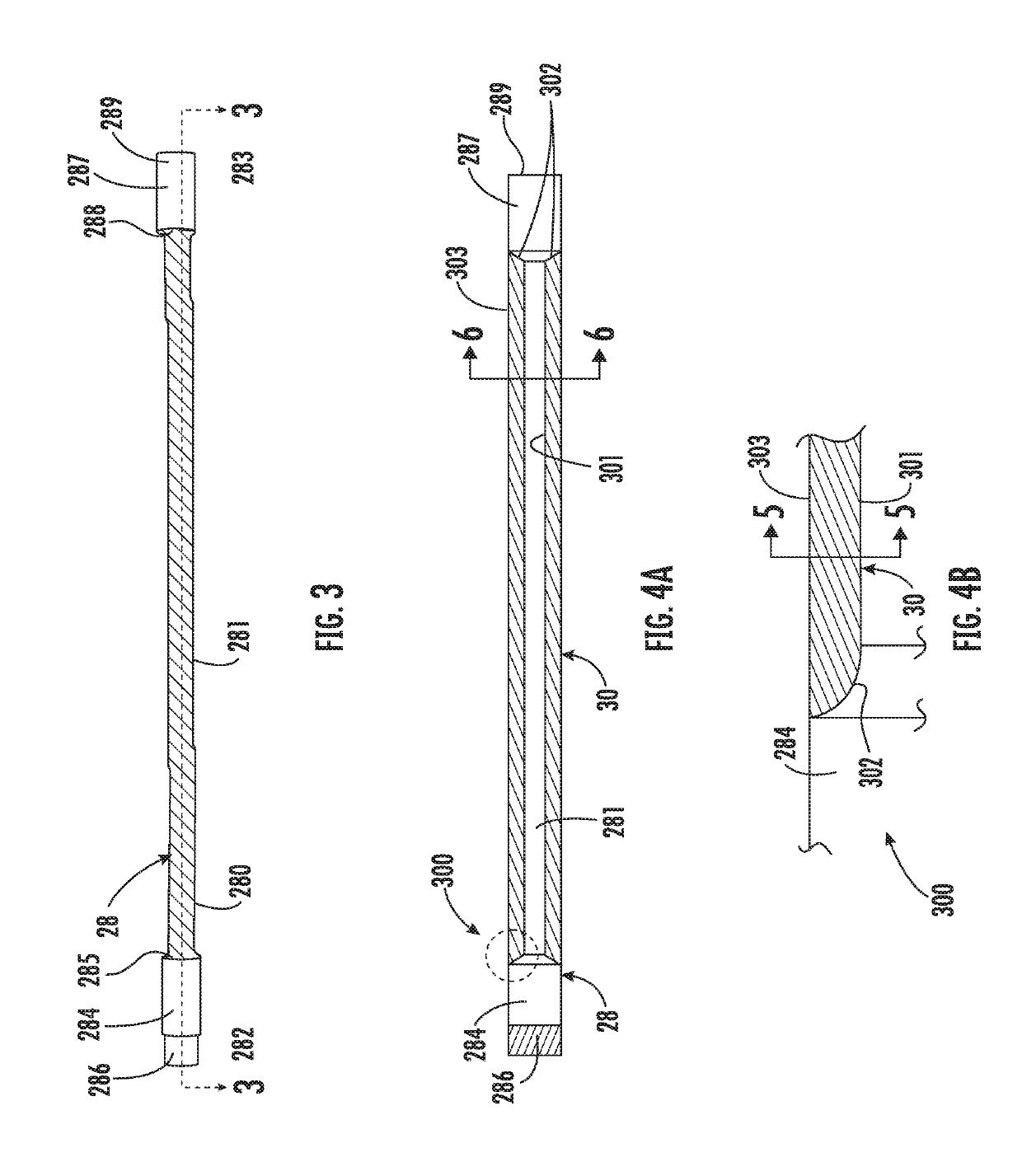
[0030]As will be described below, an uncoupled / unbonded composite wrap has been provided for an axially loaded quill shaft or another similar device. The wrap is cured over a metallic (e.g., steel or any other similar material) surface of the quill shaft and has a light weight graphite epoxy layup structure with an optional rubber interface. This structure serves to dampen and thus mitigate vibrations to which the quill shaft may be subjected to during test loads over its service lifetime. As a general matter, the following description relates to any cylindrical or non-cylindrical shaft or shaft-like device in any application where resonant frequencies of the shaft or the shaft-like device are modified by a combination of overwraps of composites and other damping materials. The resonant frequencies would be modified for any number of reasons including, but not limited to, preventing excessive loading from resonant excitation, sound profile modification, preventing vibrations from tr...


PUM

PropertyMeasurementUnit
resonance frequencyaaaaaaaaaa
vibration dampingaaaaaaaaaa
diameteraaaaaaaaaa

Abstract

A composite wrap is provided for damping vibration in an elongated quill shaft having a cylindrical body. The composite wrap includes interior layering for disposition about a cylindrical body, exterior layering configured to define an exterior composite wrap shape and sequential cured-in-place, vibration damping, fibrous epoxy layers. The sequential cured-in-place, vibration damping, fibrous epoxy layers are radially interposed between the interior and exterior layering to dampen vibrations of and / or to adjust a resonance frequency of the cylindrical body.

Description

CROSS-REFERENCE TO RELATED APPLICATION[0001]This is a non-provisional application that claims the benefit of priority to provisional application No. 62 / 211,493, which was filed on Aug. 28, 2015. The entire contents of provisional application No. 62 / 211,493 are incorporated herein by reference.FEDERAL RESEARCH STATEMENT[0002]This invention was made with government support with the United States Navy under Contract No.: N00019-06-C-0081. The government therefore has certain rights in this invention.BACKGROUND OF THE DISCLOSURE[0003]The subject matter disclosed herein relates to a composite over wrap and, more particularly, to a composite over wrap that is to be provided on a shaft for frequency control.[0004]Aircraft drive systems, such as those in aircraft used to drive aircraft rotors, utilize rotating drive shafts for power transfer and other uses. Such systems may include a plurality of quill shafts that are generally used to align complementary gearing, such as generator gearing ...

Claims


Application Information

Patent Timeline
Patent Type & Authority Patents(United States)
IPC IPC(8): F16C3/00B32B27/34B32B27/38B32B5/12F16F15/12B32B25/08F16C3/02B64C27/00B64C27/14B32B5/02B32B5/26B32B7/06B32B25/10B32B27/12B32B1/08
CPCF16F15/1201B32B5/02B32B5/12B32B5/26B32B7/06B32B25/08B32B25/10B32B27/12B32B27/34B32B27/38B64C27/001B64C27/14F16C3/023F16C3/026B32B1/08Y10T464/50B32B2255/00B32B2260/021B32B2260/046B32B2262/0269B32B2262/101B32B2262/106B32B2307/56B32B2307/748B32B2597/00B32B2605/18F16C2326/43F16F15/10F16F2224/0241F16F2230/10B64C27/12
Inventor BREMMER, JONATHANSAUER, JEFFREY G.LACKO, ROBERT A.SONG, SHIHONG G.MEESON, JR., JOHN H.
Owner SIKORSKY AIRCRAFT CORP
Why Eureka
Try Eureka