Device and method for converting thermal energy

a technology of thermal energy and converting device, which is applied in the direction of compression machines, refrigeration machines, lighting and heating apparatus, etc., can solve the problems of fundamental faulty consideration, insufficient arrangement of impellers known from the prior art, and inability to increase, so as to achieve efficient compression of working medium, increase centrifugal compression effect, and increase the effect of centrifugal acceleration

Active Publication Date: 2019-04-02
ECOP TECH
View PDF16 Cites 0 Cited by
  • Summary
  • Abstract
  • Description
  • Claims
  • Application Information

AI Technical Summary

Benefits of technology

[0026]Surprisingly, it has been proven advantageous to arrange the motor for rotation of the impeller in the same direction of rotation as the rotor having the expansion and compression channels for the working medium. If the impeller rotates in the same direction as the main rotor, the acceleration field of the main rotor may be used advantageously. Thereby, the efficiency of the impeller may be improved even with respect to an arrangement having a non-rotating housing, since the compression ratio in the impeller itself is increased due to centrifugal acceleration, and this compression has a significantly higher effectiveness than the pressure increase due to velocity changes occurring during the transition from the impeller to the discharge channel, for example.
[0033]With an increasing mass flow in the cycle process, a not permanently increasing pressure difference is observed at the impeller. According to this, especially when there is a low mass flow and high speed of the rotor, a dropping pressure difference at the impeller is caused as the mass flow increases, then the pressure difference rises again. For this reason, it is favorable to use an impeller having a gradient as steep as possible, i. e. at a certain speed of the impeller and a speed of the main rotor, a gradient dropping as steeply as possible is preferred upon reaching maximum pressure. Such a gradient is obtained in particular with multi-stage impellers. Since the characteristic curve of the process (i. e. the pressure required over the mass flow) and the characteristic curve of the blades (i. e. the pressure generated over the mass flow) usually show two intersections with only one of them being a stable operation point, a vertical characteristic curve for pressure generation would be ideal. This could be put into practice by reciprocating engines (such as piston engines), for example. However, a multi-stage pressure increase using impellers achieves a similar effect in an advantageous manner by obtaining a very steep gradient from a certain point on.
[0034]The object forming the basis of the invention is further achieved by a method of the initially mentioned type, wherein in the heat pump operating state individual flows of the working medium are guided to a point directly upstream of the impeller and introduced into the impeller substantially parallel to the rotational axis. According to this, the flows of the working medium are guided into the impeller individually and / or separated from one another and in the axial direction.
[0035]The advantages and technical effects of this method are apparent from the above explanations, to which reference can be made hereby.
[0036]Surprisingly, it has proven advantageous to rotate the impeller in the same direction of rotation as and at a higher absolute speed than the rotor having the expansion and compression channels. The rotation of the impeller in the direction of rotation of the rotor provides a higher absolute speed of the impeller, which causes a correspondingly higher centrifugal acceleration and thus a more efficient compression of the working medium. If the impeller and the rotor rotate in the same direction of rotation, the centrifugal compression effect is increased proportionally, and consequently efficiency is improved.

Problems solved by technology

However, the axial construction has the drawback that compared to the radial construction lower pressure increases can be effected, thus requiring the axial impellers to be formed multi-staged in most cases.
Extensive experiments, however, revealed that the arrangement of the impellers known from the prior art does not provide satisfactory results in generic devices in which the supply and discharge lines of the impeller are arranged rotationally within the rotor housing.
However, this consideration turned out to be fundamentally faulty.
This spin changes the characteristics of the supply flow, in particular the velocity triangles, significantly, so there was no way how dimensioning according to conventional methods could have been successful.
Typically, when changing the speed of the impeller and / or in case of varying relative flow rates, i. e. during operation outside of the design point, the inflow angles of the flow change, thereby generating an inconsistent inflow into the blade region of the impeller.
This effect reduces the effectiveness of the impeller during operation outside of the design point.

Method used


Image

  • Device and method for converting thermal energy
  • Device and method for converting thermal energy
  • Device and method for converting thermal energy

Examples


Embodiment Construction

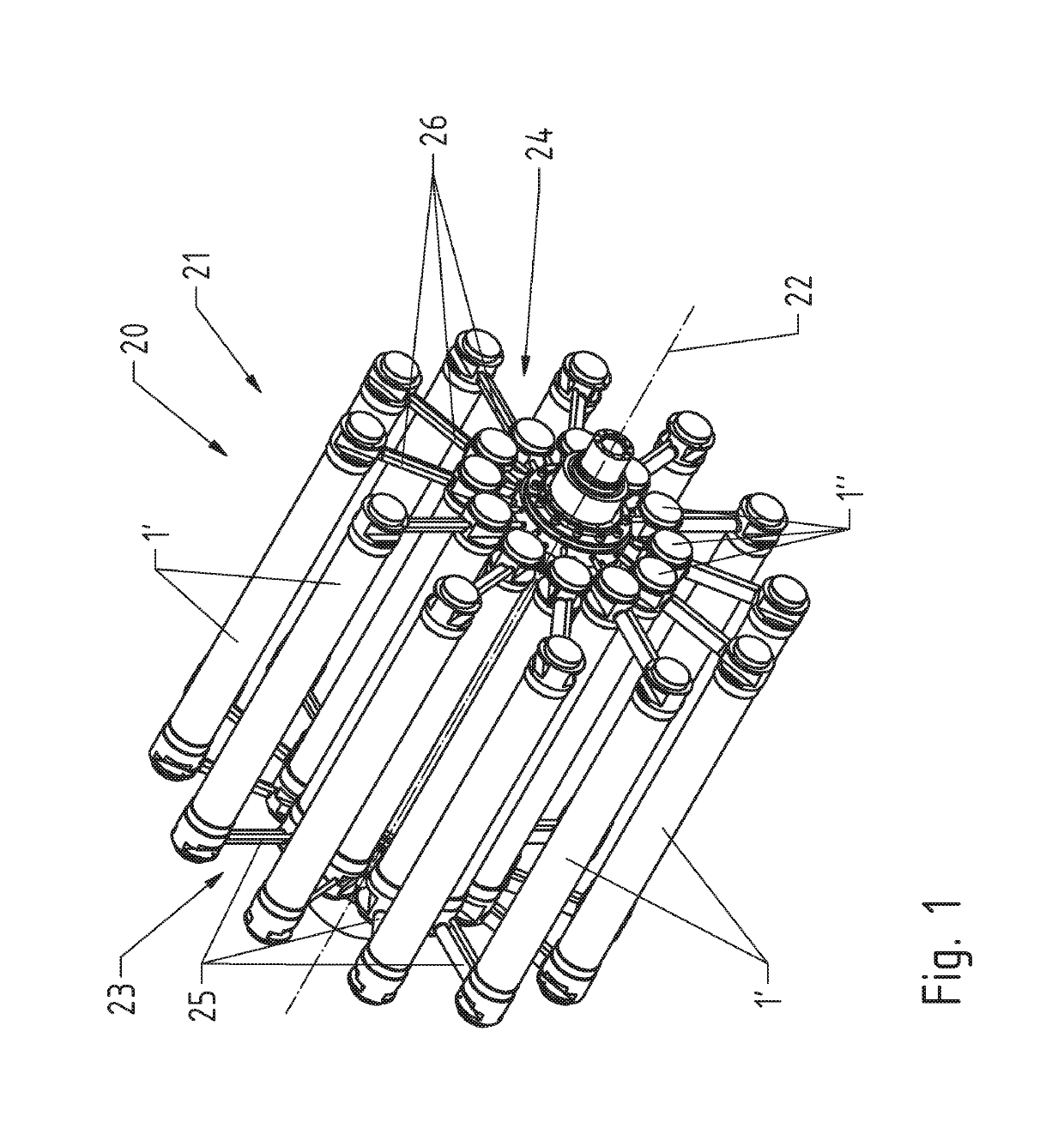
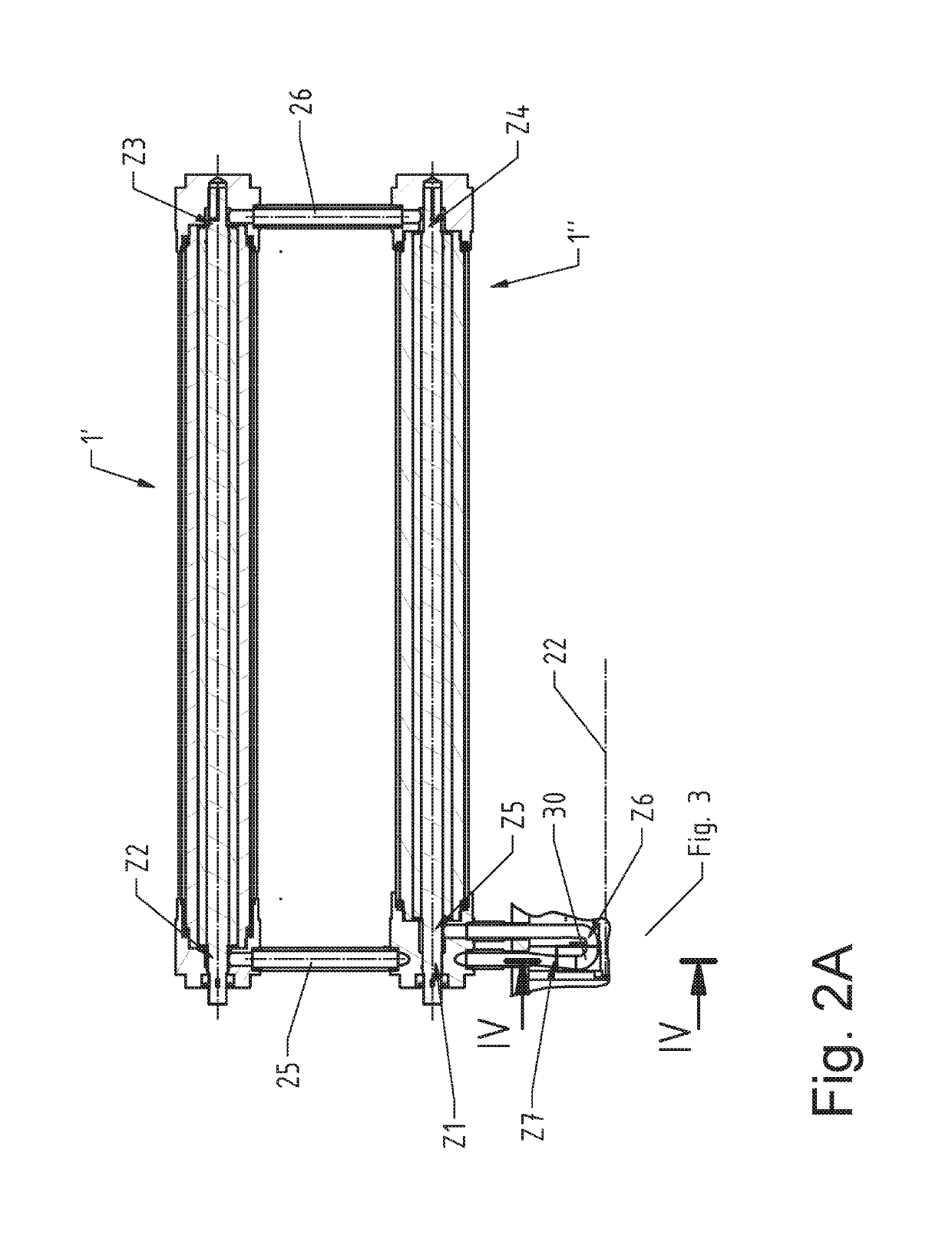
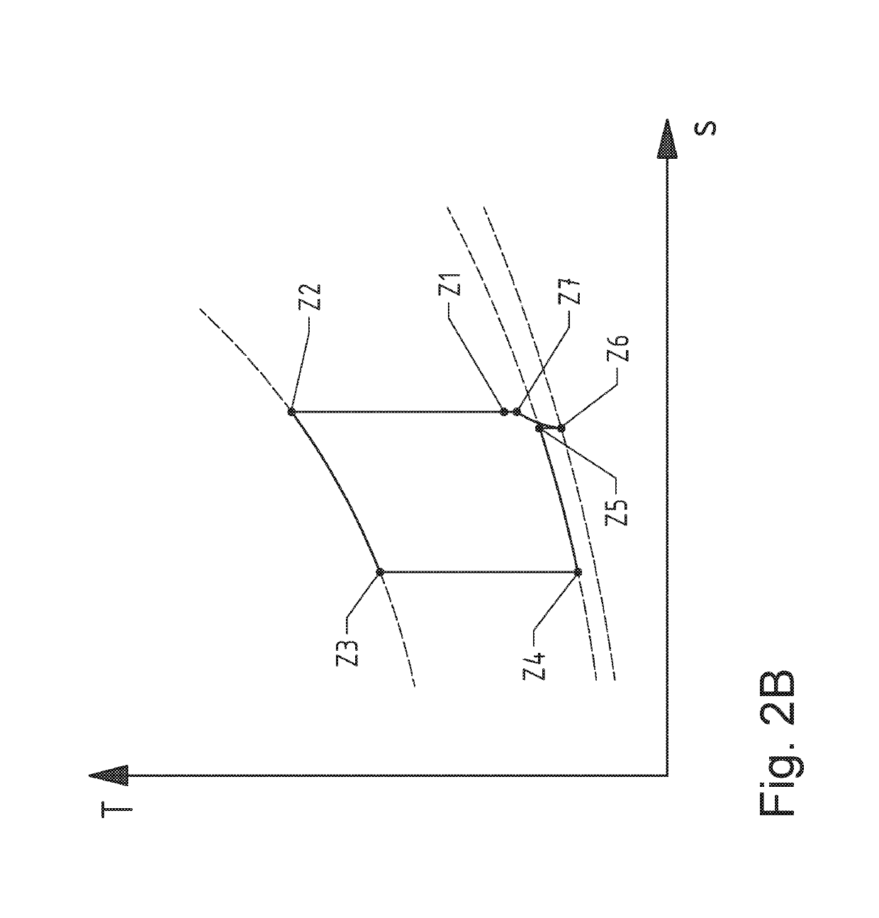
[0046]FIG. 1 shows a device 20 for converting thermal energy using mechanical energy and vice versa, which is used as a heat pump in the embodiment shown. The device 20 includes a rotor 21 which is rotatable around a rotational axis 22 by means of a motor (not illustrated). The rotor 21 includes a compressor unit 23 and an expansion unit 24, which have flow channels for a working medium. When flowing through the rotor 21, the working medium, for example a noble gas, passes through a closed cycle process, which includes the working steps of a) compression of the working medium, b) heat exchange between the working medium and a heat exchange medium in an outer heat exchanger 1′, c) expansion of the working medium, and d) heat exchange between the working medium and a heat exchange medium in an inner heat exchanger 1″. For this purpose, the compressor unit 23 has compression channels 25 extending substantially in the radial direction, in which the working medium flows to the outside in...


PUM


Abstract

A device and a method for converting low temperature thermal energy into high temperature thermal energy using mechanical energy with a rotor for a working medium passing through a closed cycle. The rotor has a compressor unit with compression channels and an expansion unit with expansion channels, and has heat exchangers for exchanging heat between the working medium and a heat exchange medium. The device has an impeller which can be rotated relative to the rotor. The impeller is arranged between supply channels which conduct the flow of the working medium in the heat pump and at least one rotor discharge channel which discharges the flow of the working medium in the heat pump. The supply channels have outlet sections which extend up to a point directly upstream of an inlet opening of the impeller such that flows of the working medium are conducted out of the supply channels.

Description

CROSS REFERENCE TO RELATED APPLICATIONS[0001]The present application is a U.S. National Phase of International Patent Application Serial No. PCT / AT2015 / 050098, entitled “DEVICE AND METHOD FOR CONVERTING THERMAL ENERGY,” filed on Apr. 22, 2015. International Patent Application Serial No. PCT / AT2015 / 050098 claims priority to Austrian Patent Application No. A 50296 / 2014, filed on Apr. 23, 2014. The entire contents of each of the above-cited applications are hereby incorporated by reference in their entirety for all purposes.TECHNICAL FIELD[0002]The invention relates to a device for converting thermal energy with a low temperature into thermal energy with a higher temperature and vice versa using mechanical energy, having a rotor rotatably arranged around a rotational axis for a working medium passing through a closed cycle process, wherein the rotor has a compressor unit with multiple compression channels, in which flows of the working medium may be guided substantially radially to the...

Claims


Application Information

Patent Timeline
Patent Type & Authority Patents(United States)
IPC IPC(8): F25B3/00F25B9/00
CPCF25B9/00F25B3/00
Inventor ADLER, BERNHARD
Owner ECOP TECH
Why Eureka
Try Eureka