
Foldable crutch

a crutch and folding technology, applied in the field of folding crutches, can solve the problems of large length of the crutch, unsatisfactory shock absorption effect, inconvenient storage and transportation in the car, etc., and achieve the effect of convenient adjustment and assembly stability

Active Publication Date: 2019-04-16
CHU ZOOEY CHI TIEN +1
View PDF11 Cites 8 Cited by
  • Summary
  • Abstract
  • Description
  • Claims
  • Application Information

AI Technical Summary

Benefits of technology

This patent aims to provide a foldable crutch that is easy to adjust and assemble, stable, and can be used in a wide range of applications. Additionally, it enhances the buffering effect and use comfort of the crutch, while reducing the likelihood of it falling off the user. The length of the crutch can also be adjusted for wider applications.

Problems solved by technology

Firstly, the underarm crutch has a considerable length larger than the spacing between the armpit of the user to the ground, which is inconvenient to storage and transportation in a car.
Secondly, the soft tip 11′ provides an unsatisfactory shock absorbing effect, failing to provide comfort use.
Thirdly, the pad 3′ and the handgrip 4′ are difficult to adjust in height and, thus, cannot be used by different users.
However, falling off of the underarm crutch still occurs.
However, the assembly and folding requires rotation of the buckle.
Furthermore, the upper and lower rod units can still wobble or even disengage from each other when the buckle is not tightened.
Furthermore, the upper and lower rod units, when disengaged from each other, are not securely connected, failing to provide folding integrity.
However, the spring and corresponding components increase the costs in the components and assemblage.
However, the flexible limb could bend excessively when subject to a larger force, leading to a great change in the length of the crutch and adversely affecting the use safety.

Method used


Image

  • Foldable crutch
  • Foldable crutch
  • Foldable crutch

Examples


Embodiment Construction

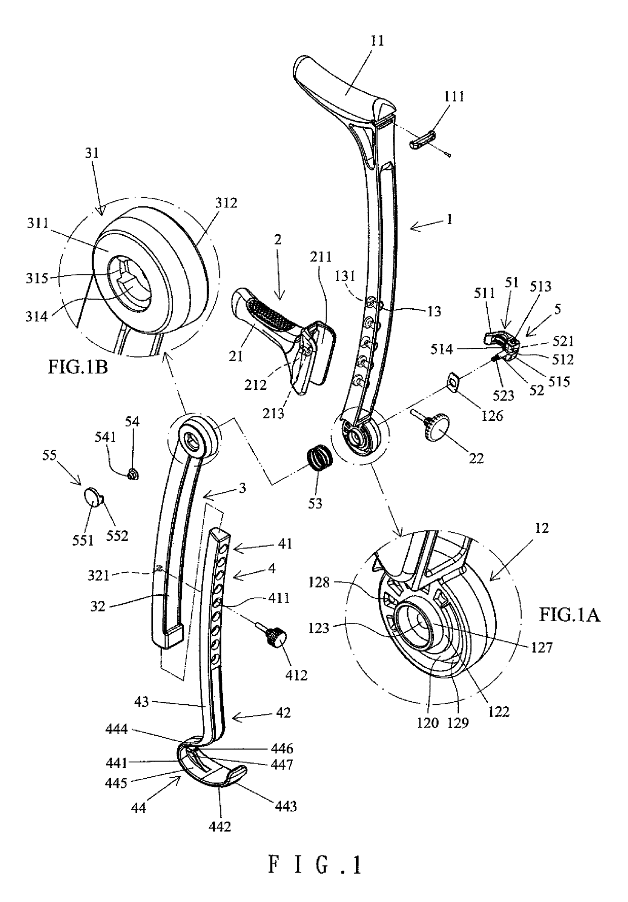
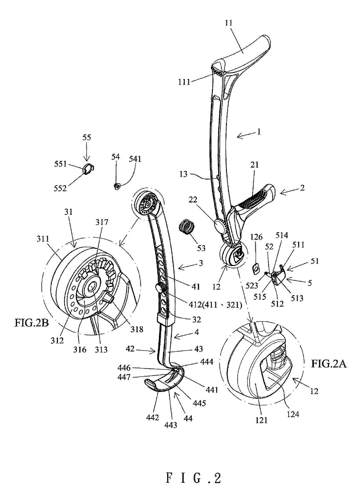
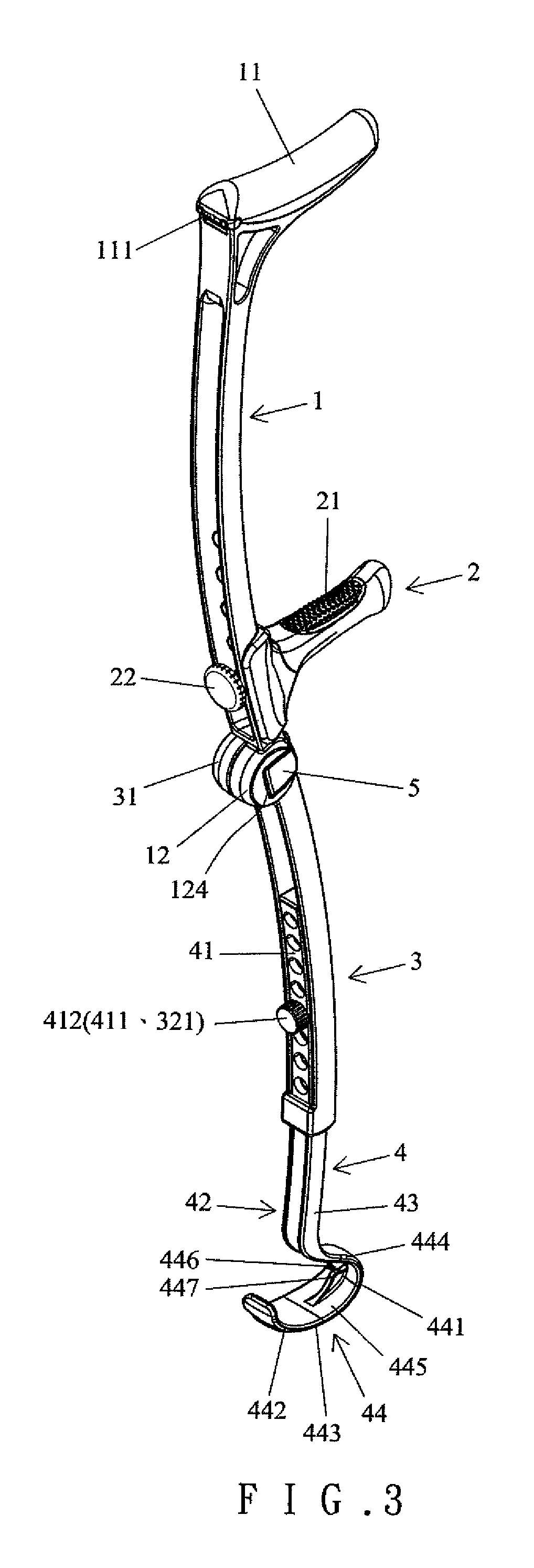
[0039]With reference to FIGS. 1-5, a foldable crutch of an embodiment according to the present invention includes an upper rod 1, a handle 2, a lower rod 3, a supporting rod 4, and a locking device 5. The upper rod 1 includes a pad portion 11 on a top end thereof. The upper rod 1 further includes a first coupling portion 12 on a bottom end thereof. The upper rod 1 further includes a central portion having a plurality of coupling holes 13 located at different heights. Each of the plurality of coupling holes 13 includes an end having a countersink 131 with a larger diameter. An anti-slip member 111 is disposed on a rear side of the pad portion 11. When the foldable crutch props against a wall (not shown), the anti-slip member 111 avoids slipping of the foldable crutch and, thus, provides a positioning effect. The first coupling portion 12 is circular in cross section. The first coupling portion 12 includes a first outer surface 121 and a first inner surface 122. The first coupling por...


PUM


Abstract

A foldable crutch includes an upper rod having a pad portion on a top end thereof and a first coupling portion at a bottom end thereof. The first coupling portion includes at least one positioning groove and a receiving groove. A handle is disposed on the upper rod. A lower rod includes an upper end having a second coupling portion mounted to the first coupling portion. The second coupling portion includes a positioning member for coupling with the positioning groove or the receiving groove. A turn knob is mounted to the first coupling portion. An axle extends through the first and second coupling portions and is pivotably connected to the turn knob. An elastic element biases the first and second coupling portions to disengage the positioning member from the at least one positioning groove when the turn knob is in the unlocking position.

Description

BACKGROUND OF THE INVENTION[0001]The present invention relates to a foldable crutch and, more particularly, to a crutch that can be extended or folded and that provides easy adjustment, assembling stability, and wider applications.[0002]Walking, aids include walking sticks, forearm crutches, underarm crutches, etc. FIG. 13 shows a conventional underarm crutch including a leg portion 1′, a connecting frame 2′, a pad 3′, and a handgrip 4′. A soft tip 11′ is attached to a lower end of the leg portion 1′. The connecting frame 2′ includes two side bars 21′. The pad 3′ is fixed to upper ends of the side bars 21′. The upper section of the leg portion 1′ is fixed to lower ends of the two side bars 21′. The handgrip 4′ is interconnected between intermediate portions of the two side bars 21′. Thus, a user can place his or her armpit on the pad 3′ while gripping the handgrip 4′. The tip 11′ forms a support when contacting with the ground.[0003]However, the above underarm crutch has several dis...

Claims


Application Information

Patent Timeline
IPC IPC(8): A61H3/02A45B9/00
CPCA61H3/02A61H2201/1635A61H2201/1614A61H2201/0161A45B2009/005A45B2009/007A45B9/00A45B9/04A61H2003/0211A61H3/0244A61H2201/0126A61H2201/0173A61H2201/0192A61H2201/1616
Inventor CHU, ZOOEY CHI-TIENPAN, DOUGLAS
Owner CHU ZOOEY CHI TIEN
Learn More