Actuating dump valve

Active Publication Date: 2019-04-16
TECH HLDG
View PDF13 Cites 0 Cited by
  • Summary
  • Abstract
  • Description
  • Claims
  • Application Information

AI Technical Summary

Benefits of technology

[0007]The present disclosure presents several technical advantages. For example, a valve assembly that selectively provides multiple flow paths and complies with various safety regulations for robotic milking systems. The valve assembly is configured to provide a block-bleed-block system

Problems solved by technology

Using multiple valve devices in series may increase the number of parts used, cost, and the overall physical dimensions of the valve system.
Using multiple valve devices in series may also increase the complexity of controlling the valve devices, which may prevent the valve devices from sa

Method used


Image

  • Actuating dump valve
  • Actuating dump valve
  • Actuating dump valve

Examples


Embodiment Construction

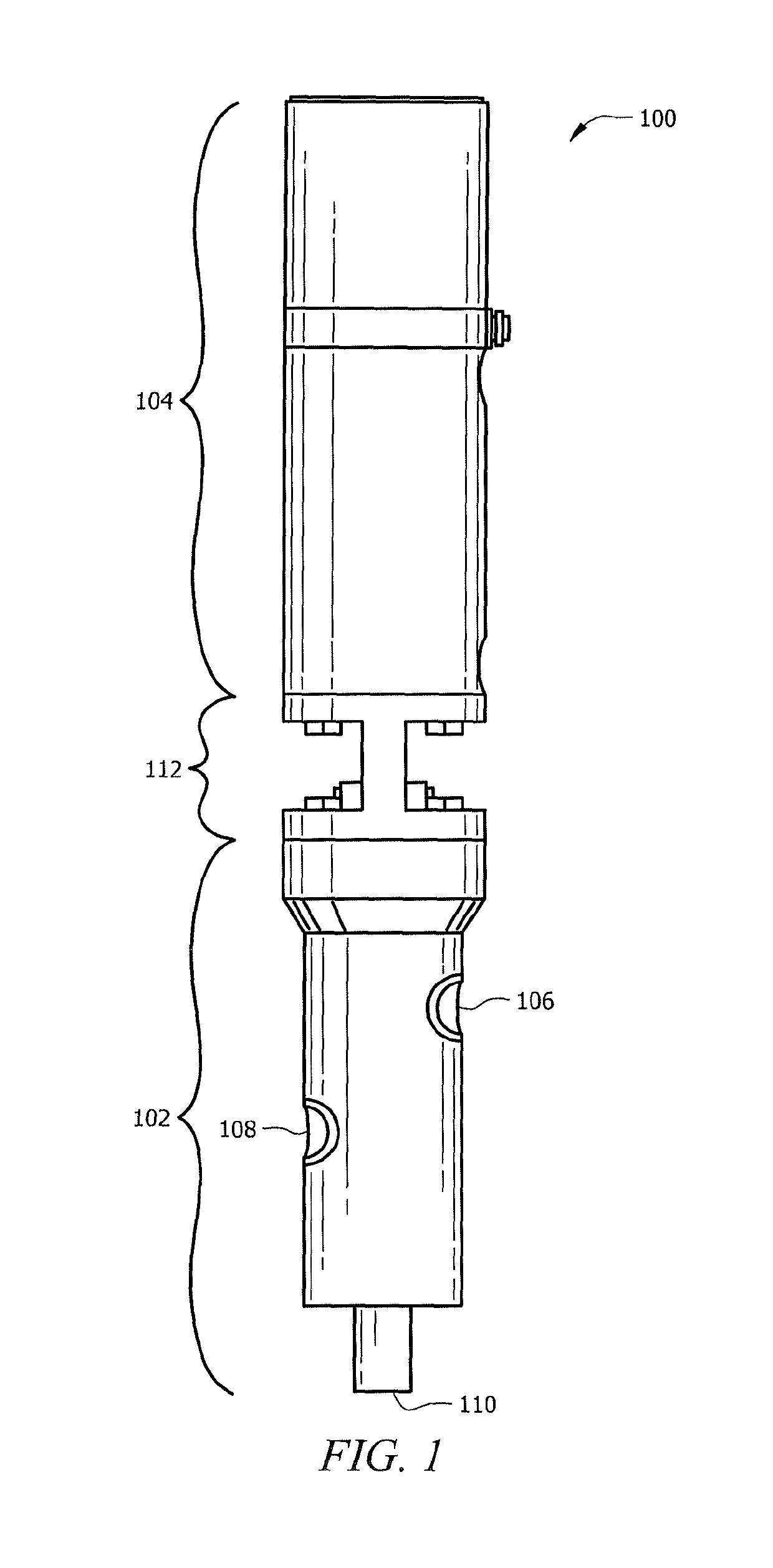
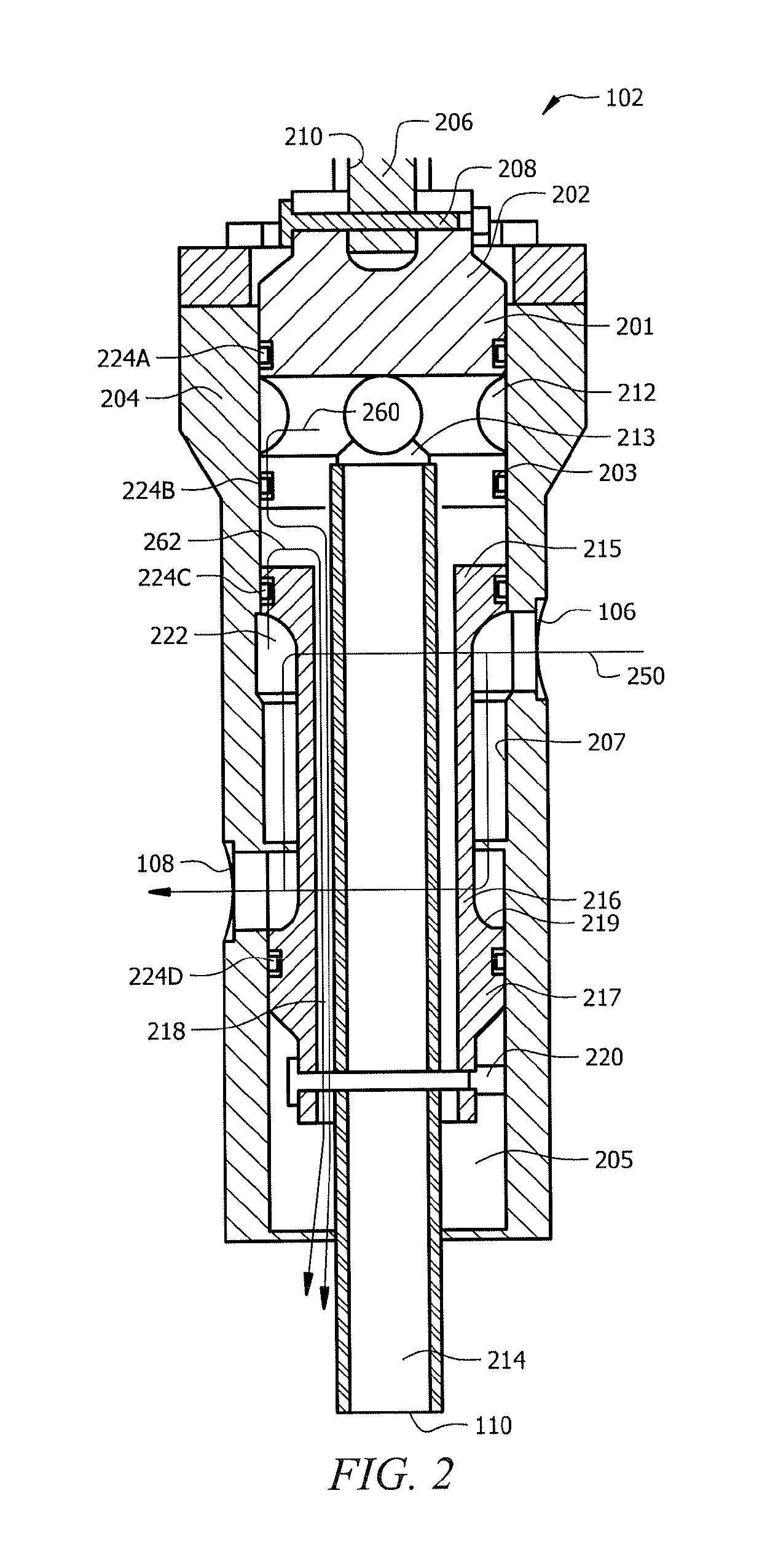
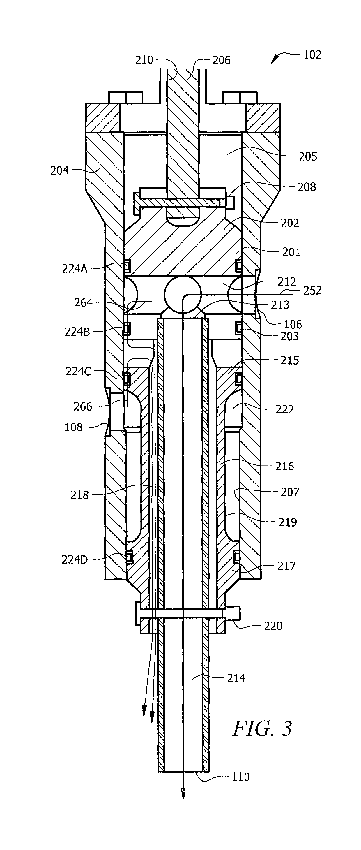
[0017]Disclosed herein are various embodiment of a valve assembly comprising a reconfigurable valve. The valve is configured to use a moveable piston disposed within the bore of the valve to selectively provide flow paths between an input port and output ports of the valve. In a first configuration, the valve may be configured to provide a first flow path from an input port to a first output port via a path along a portion of an exterior of the piston within the bore of the housing. For example, in the first configuration the valve may be configured such that a fluid (e.g. raw milk) flows from the input port to the first output port around the peripheral of a portion of the piston.

[0018]In a second configuration, the valve may be configured to provide a second flow path from the input port to a second output port (e.g. a dumping port) via a path within the piston. For example, in the second configuration the valve may be configured such that a fluid (e.g. a cleaning fluid) flows fro...


PUM


Abstract

An apparatus that includes a housing with an input port and a first output port. A piston is disposed within a bore of the housing and includes a bypass via disposed transversely within the bore and a bypass tube disposed longitudinally within the bore. The bypass tube is configured to provide a flow path from the bypass via to a second output port on the bypass tube. The piston includes a sleeve disposed concentrically around the bypass tube. An interior chamber is defined by an exterior surface of the sleeve and an interior surface of the bore of the housing. The piston is configurable between a first configuration that provides a first flow path between the input port and the first output port via the interior chamber and a second configuration that provides a second flow path between the input port and the second output port via the bypass tube.

Description

TECHNICAL FIELD[0001]This disclosure relates generally to valve devices, and more specifically to an actuating valve device.BACKGROUND[0002]Valve devices used in automated milking systems and robotic milking applications are required to comply with various safety regulations such as preventing fluid contamination. Existing valve devices may be configured to employ multiple valve devices in series to meet such safety requirements. Using multiple valve devices in series may increase the number of parts used, cost, and the overall physical dimensions of the valve system. Using multiple valve devices in series may also increase the complexity of controlling the valve devices, which may prevent the valve devices from safely reverting to a safe state in the event of a system failure. Other valve systems may use backflush valves which are difficult to clean and manufacture. Backflush valves employ a double-acting cylinder and are also unable to safely revert to a safe state in the event of...

Claims


Application Information

Patent Timeline
IPC IPC(8): F16K11/07A01J5/04A01J7/02
CPCF16K11/0716A01J7/02A01J5/04Y10T137/0424A01J5/044
Inventor OSTERBRINK, BRIAN E.GODFREY, ROBERT J.ZELL, CRAIG M.
Owner TECH HLDG
Why Eureka
Try Eureka