Spherical linkage type surgical robotic arm
a robotic arm and spherical linkage technology, applied in the field of robotics, can solve the problems of reducing the readability of surgeons, requiring complicated calculations and precise control, and a common structure of conventional robotic arms, so as to reduce the calculation burden and improve the control and allocation of robotic arms
- Summary
- Abstract
- Description
- Claims
- Application Information
AI Technical Summary
Benefits of technology
Problems solved by technology
Method used
Image

Examples
first embodiment
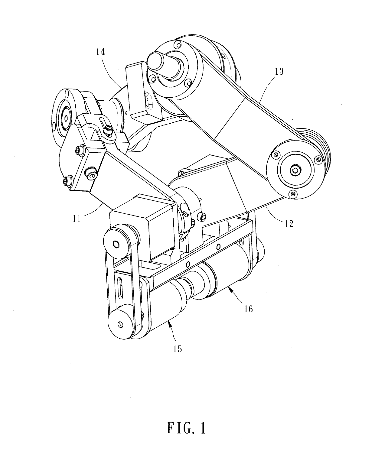
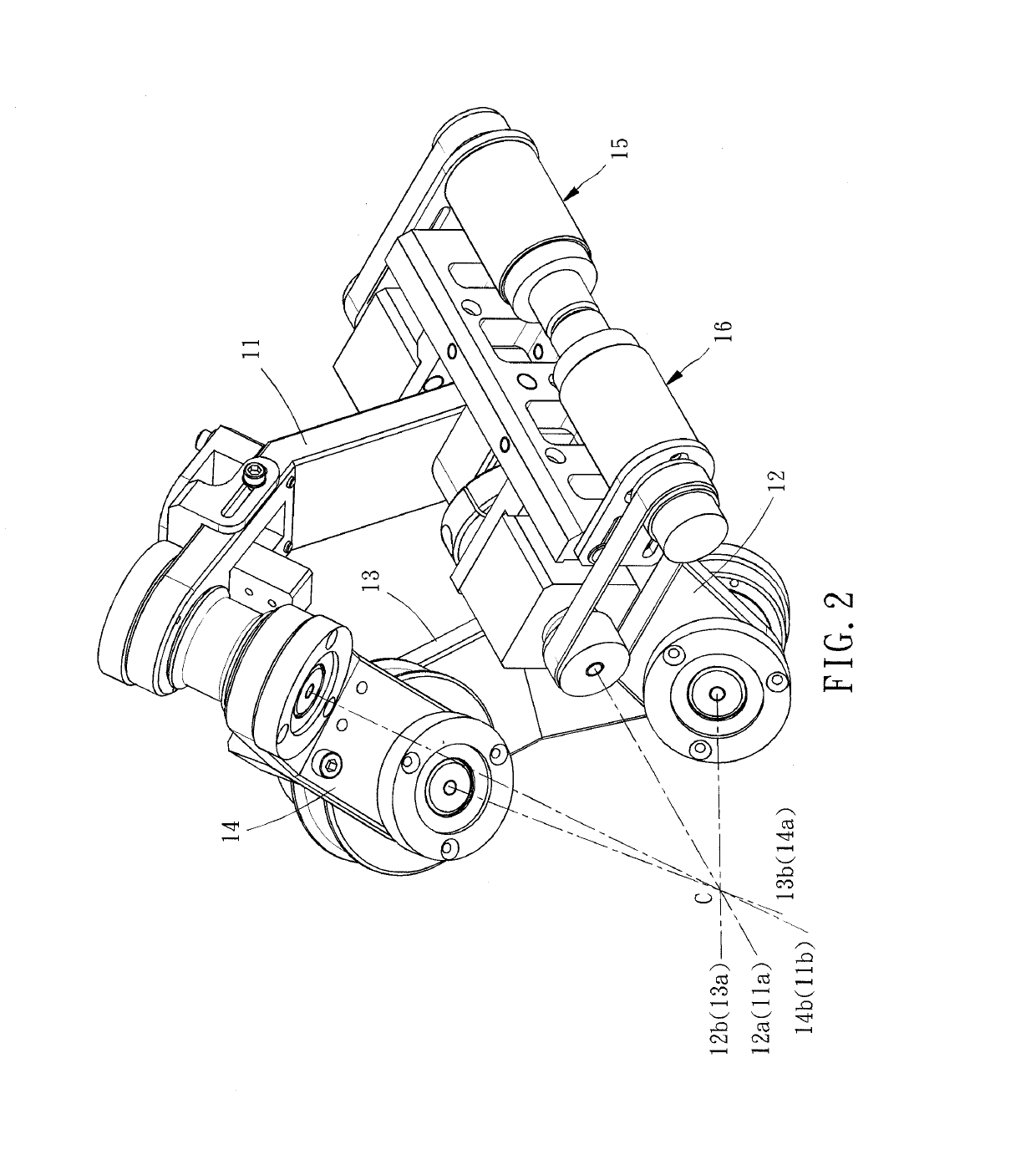
[0025]Referring to FIGS. 1-3, a spherical linkage type surgical robotic arm in accordance with the present invention is shown turnable around a center of spherical rotation C. The spherical linkage type surgical robotic arm comprises a first curved bar 11, a second curved bar 12, a third curved bar 13 and a fourth curved bar 14.
[0026]It is to be noted that the axle center described in this specification is a virtual axis about which an object is turned.
[0027]The first curved bar 11 has a first axis center 11a and a second axis center 11b respectively located at two opposite ends thereof and passed through the center of spherical rotation C.
[0028]The second curved bar 12 is of equal length relative to the first curved bar 11, having a third axis center 12a and a fourth axis center 12b respectively located at two opposite ends thereof and passed through the center of spherical rotation C. Further, the third axis center 12a coincides with the first axis center 11a.
[0029]The third curv...
second embodiment
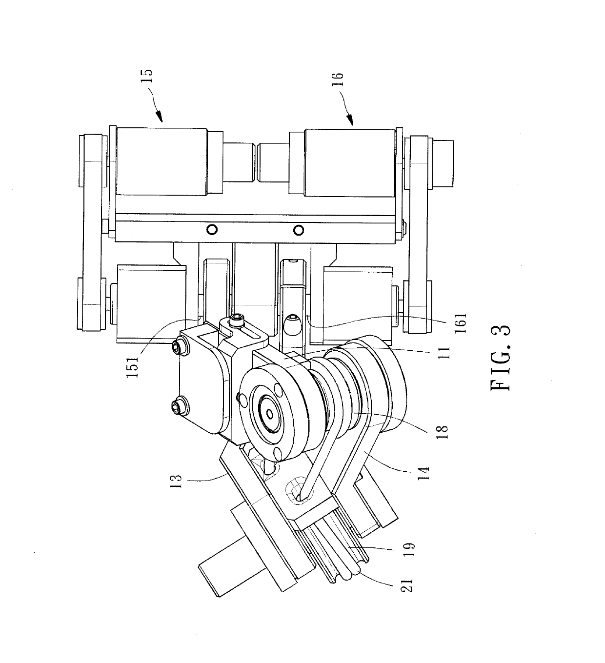
[0041]During the operation of the present invention, due to the installation of the first proportional wheel 18 and the second proportional wheel 19, there is a turn proportional relationship between the instrument bar 17 and the first curved bar 11, and therefore the turning angle of the surgical instrument mounted at the instrument bar 17 can be reduced, bringing to the surgeon better readability of the data being displayed on the surface of the surgical instrument than conventional mechanical arm designs.
third embodiment
[0042]Referring to FIG. 7, a spherical linkage type surgical robotic arm in accordance with the present invention is shown turnable about a center of spherical rotation. The spherical linkage type surgical robotic arm comprises: a first curved bar 31, a second curved bar 32, a third curved bar 33, a fourth curved bar 34, a ground bar 35, an instrument bar 36, a first proportional wheel 37, a second proportional wheel 38 and a flexible element 39.
[0043]The first curved bar 31 has a first axis center 31a and a second axis center 31b respectively located at two opposite ends thereof and passed through the center of spherical rotation C.
[0044]The second curved bar 32 has a third axis center 32a and a fourth axis center 32b respectively located at two opposite ends thereof and passed through the center of spherical rotation C.
[0045]The third curved bar 33 has a fifth axis center 33a and a sixth axis center 33b respectively located at two opposite ends thereof and passed through the cente...
PUM
 Abstract
Description
Claims
Application Information
 - R&D
- Intellectual Property
- Life Sciences
- Materials
- Tech Scout
- Unparalleled Data Quality
- Higher Quality Content
- 60% Fewer Hallucinations
Browse by: Latest US Patents, China's latest patents, Technical Efficacy Thesaurus, Application Domain, Technology Topic, Popular Technical Reports.
© 2025 PatSnap. All rights reserved.Legal|Privacy policy|Modern Slavery Act Transparency Statement|Sitemap|About US| Contact US: help@patsnap.com