Drive support apparatus

a technology of supporting apparatus and drive shaft, which is applied in the direction of traffic control system, transportation and packaging, instruments, etc., can solve the problems of not providing drive support, map-matching may also be prone to matching errors, and the current position error is determined

Active Publication Date: 2019-04-23
DENSO CORP
View PDF10 Cites 0 Cited by
  • Summary
  • Abstract
  • Description
  • Claims
  • Application Information

AI Technical Summary

Benefits of technology

[0010]It is an object of the present disclosure to provide a drive support apparatus that is capable of preventing a lack of the drive support in an actually-required situation, while also preventing a provision of an unnecessary drive support.
[0019]Therefore, in the present disclosure, when the reliability of the map matching is high, whether to suppress the drive support is determined by utilizing the road map information. In such manner, an unnecessary drive support is prevented from being provided for the driver of the self-vehicle.
[0020]On the other hand, when the reliability of the map matching is low, the node determiner does not perform a determination. That is, when the reliability of the map matching is low, whether to suppress the drive support is not determined by utilizing the road map information. Then, whether to provide the drive support is determined based on whether any cross point is formed between (i) the self-vehicle predicted path from the self-vehicle path predictor, which is derived from the current position and the travel direction of the self-vehicle determined by the self-vehicle positioner, and (ii) the nearby vehicle predicted path. In such manner, a lack of drive support, i.e., a suppression of the drive support, in a drive support required situation is prevented.

Problems solved by technology

The navigation signal from the satellite, however, includes a position determination error, which may result in an error of the determined current position, i.e., a position of the subject vehicle that is actually traveling on a certain road may sometimes be determined as a position other than, outside of, a traveling road due to the position determination error in a “GNSS current position” that is derived from the GNSS navigation signal described above.
However, the map-matching may also be prone to a matching error, e.g., may wrongly match the travel locus of the vehicle to a road, i.e., to a road shape that is not completely matching with the travel locus, when a road shape somewhat close to the travel locus is found at a proximity of the current position, or in other words, a true / actual road on which the vehicle is traveling.
Thus, the drive support based always on the map-matched current position may not yield an intended result, i.e., may lead to a situation in which the drive support is not provided when the support is actually needed.
However, by not performing the map-matching, a collision possibility may be wrongly determined based on a wrong prediction of crossing of the two roads, i.e., the road traveled by the subject vehicle and the road traveled by the other vehicle which are actually not crossing with each other.
Based on such a wrong prediction, an unnecessary drive support is provided for the driver.
In other words, even when a cross point between the self-vehicle predicted path and the nearby vehicle predicted path exists, in case that such a cross point is not located in an intersection, a possibility of collision between the self-vehicle and the nearby vehicle is low.
When the intersection node is not found in the determination area, it is highly possible that the cross point is not located in an intersection corresponding to the intersection node, and when the cross point is not located in an intersection, the collision possibility of the self-vehicle and the nearby vehicle is low.
On the other hand, when the reliability of the map matching is low, the node determiner does not perform a determination.
That is, when the reliability of the map matching is low, whether to suppress the drive support is not determined by utilizing the road map information.

Method used


Image

  • Drive support apparatus
  • Drive support apparatus
  • Drive support apparatus

Examples


Embodiment Construction

[0035]Hereafter, an embodiment of the present disclosure is described based on the drawing.

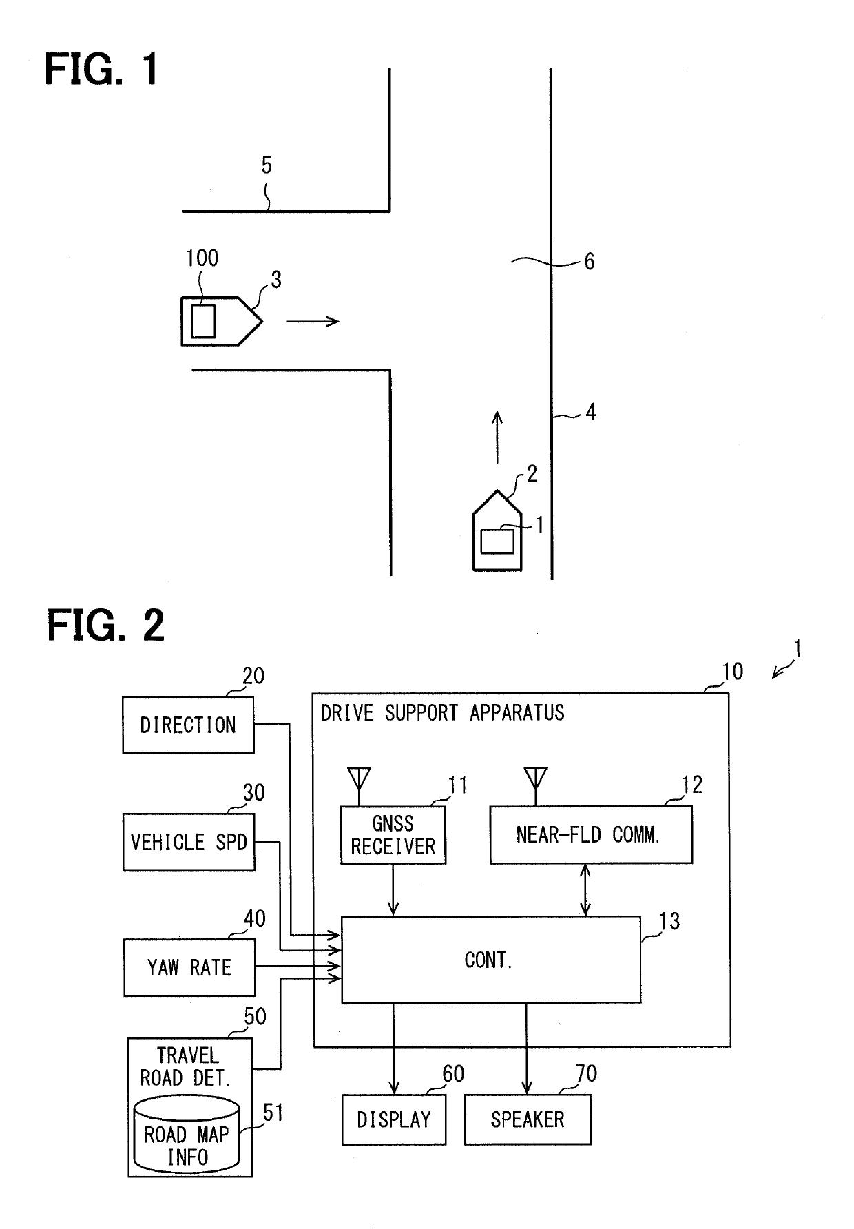
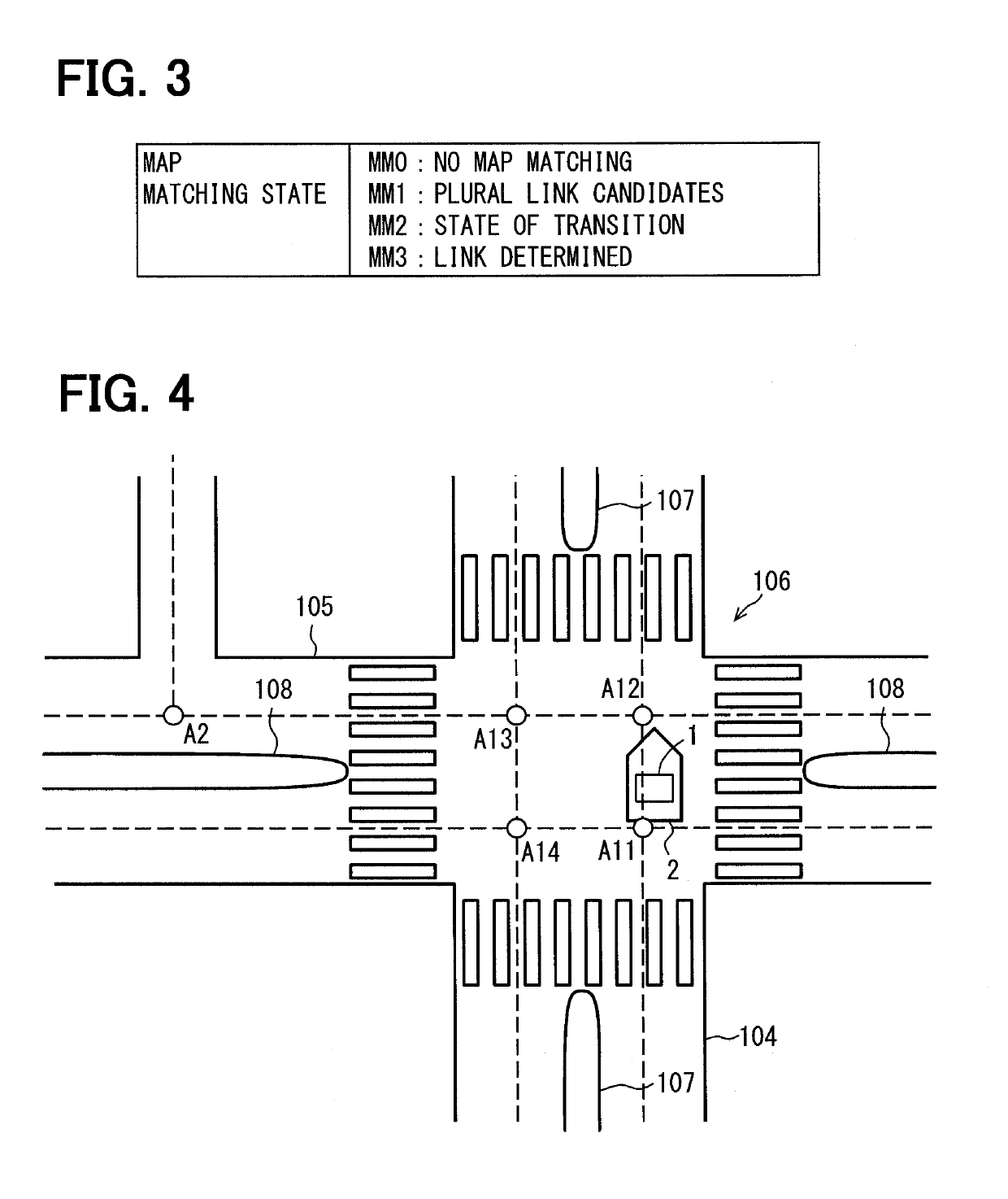
[0036]As shown in FIG. 1, a vehicle (henceforth, self-vehicle) 2 carrying a drive support system 1 travels on a road 4. In a state shown in FIG. 1, another vehicle (henceforth, nearby vehicle) 3 exists at the proximity of the self-vehicle 2. The nearby vehicle 3 travels on an intersection road 5 that intersects the road 4 on which the self-vehicle 2 travels, toward an intersection 6.

[0037]The nearby vehicle 3 has a drive support system 100 disposed thereon. Although the numeral 100 is different from the numeral 1, the drive support system 100 has the same configuration as the drive support system 1.

[0038][Configuration of the Drive Support System 1]

[0039]As shown in FIG. 2, the drive support system 1 is provided with a drive support apparatus 10, a direction sensor 20, a vehicle speed sensor 30, a yaw rate sensor 40, a travel road determiner 50, a display 60, and a speaker 70.

[0040]The drive s...


PUM


Abstract

A drive support apparatus includes: a reliability determiner determining a reliability of a map matching, an area definer defining a determination area to include a cross point between a self-vehicle predicted path and a nearby vehicle predicted path, an intersection node finder determining an intersection node in a travel direction of the self-vehicle based on a high map matching reliability, and a node determiner determining whether the intersection node is found in the determination area. When no intersection node is found in the determination area, a drive support level is suppressed, and when the reliability is low, drive support is provided depending on whether the cross point between the self-vehicle predicted path and the other vehicle predicted path is found. Thus, lack of the drive support in a support-required situation is prevented, while preventing a provision of an unnecessary drive support.

Description

CROSS REFERENCE TO RELATED APPLICATION[0001]The present application is based on and claims the benefit of priority of Japanese Patent Application No. 2016-005473, filed on Jan. 14, 2016, the disclosure of which is incorporated herein by reference.TECHNICAL FIELD[0002]The present disclosure generally relates to a drive support apparatus that supports a drive operation of a driver of a vehicle, especially regarding a drive support that is provided based on a prediction of a collision between vehicles.BACKGROUND INFORMATION[0003]A drive support apparatus for, for example, collision prediction and preventing collision between two vehicles is disclosed in a patent document, Japanese Patent Laid-Open No. 2008-97413, (Patent document 1). From such drive support apparatus, the drive support is provided for a driver of a subject vehicle having the apparatus in the following manner. That is, the subject vehicle bi-directionally communicates with other vehicle while predicting a future vehicle...

Claims


Application Information

Patent Timeline
Patent Type & Authority Patents(United States)
IPC IPC(8): G08G1/16G01C21/30H04B1/3822H04W4/40H04W4/024H04W4/029H04W4/46
CPCH04W4/40G08G1/161G01C21/30H04B1/3822B60W30/08G08G1/09626G08G1/163H04W4/029H04W4/46H04W4/024
Inventor ANDO, MOTONORI
Owner DENSO CORP
Why Eureka
Try Eureka