Displacement encoder

a technology of displacement encoder and encoder, which is applied in the direction of converting sensor output optically, instruments, measurement devices, etc., can solve the problems of increasing the distance between the optical elements, and increasing the structure so as to achieve the effect of increasing the size of the displacement encoder and increasing the structur

Active Publication Date: 2019-04-30
MITUTOYO CORP
View PDF13 Cites 0 Cited by
  • Summary
  • Abstract
  • Description
  • Claims
  • Application Information

AI Technical Summary

Benefits of technology

[0012]The present invention has been made in view of the above-described circumstances and an object of the present invention is to provide a displacement encoder capable of improving position detection accuracy by removing effects of unwanted diffracted light.
[0058]According to the present invention, it is possible to provide a displacement encoder capable of improving position detection accuracy by removing unwanted effects of unnecessary diffracted light.

Problems solved by technology

However, there are the following problems in the above-described displacement encoders disclosed in of Japanese Patent No. 2619566, Japanese Patent No. 4856844, and “Optical Encoder Using Metallic Surface Grating”.
As a result, the size of the displacement encoder would be increased and the structure thereof could become complicated.
However, when diffracted light orders need to be completely separated, the distance between the optical elements needs to be increased, because the distance by which different orders of diffracted light are separated from each other could not otherwise be increased.

Method used


Image

  • Displacement encoder
  • Displacement encoder
  • Displacement encoder

Examples


first exemplary embodiment

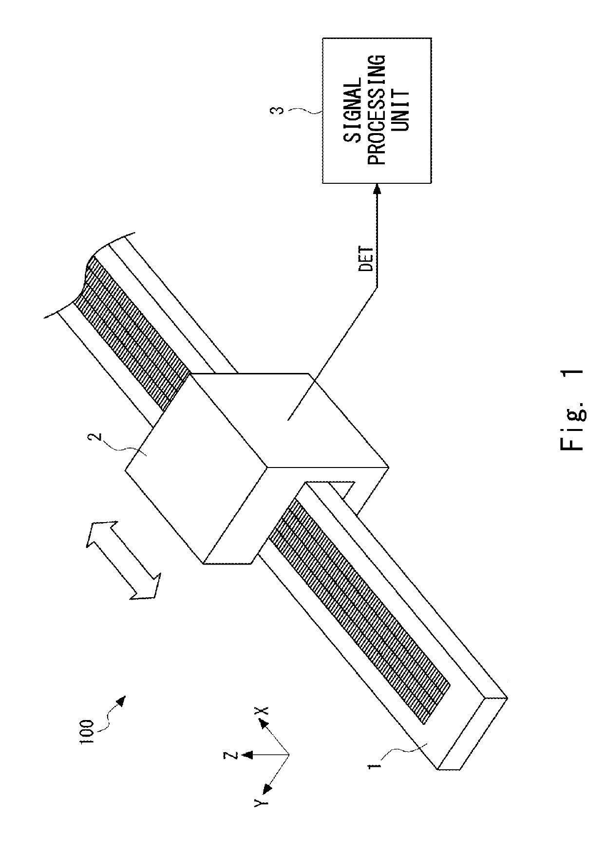
[0089]An optical displacement encoder according to a first exemplary embodiment of the present invention is explained. FIG. 1 is a perspective view showing a general configuration of an optical displacement encoder 100 according to the first exemplary embodiment. An example case where the optical displacement encoder 100 is constructed as a transmission-type displacement encoder is explained hereinafter. As shown in FIG. 1, the optical displacement encoder 100 includes a scale 1, a detection head 2, and a signal processing unit 3. The scale 1 and the detection head 2 are configured so that they can be moved relative to each other along a measurement direction (an X-axis direction in FIG. 1) which is in parallel with the longitudinal direction of the scale 1. A pattern used for position detection is formed in the scale 1. When light is applied (i.e., emitted) to the pattern, interference light is generated. The detection head 2 detects a change in the interference light in the measur...

example 1

[0109]FIG. 5 shows a relation between interference fringes and light-receiving elements according to Example 1. In Example 1, the number of arranged light-receiving elements is ten and the period (i.e., the cycle) with which the light-receiving elements are arranged (hereinafter referred to as an “arrangement period”) is equal to the fundamental period P of the interference fringes. Further, the width W of each of the light-receiving elements is 0.5 times the fundamental period P (i.e., a half of the fundamental period P) of the interference fringes. Note that in this example, light-receiving elements 11A and light-receiving elements 11B are alternately arranged.

[0110]As for the light-receiving elements 11A, they are arranged with a period 2P, i.e., twice the fundamental period P as shown in FIG. 5. As for the light-receiving elements 11B, they are also arranged with the period 2P, i.e., twice the fundamental period P. That is, the light-receiving elements 11A detect an optical inte...

example 2

[0114]FIG. 6 shows a relation between interference fringes and light-receiving elements according to Example 2. In Example 2, the number of arranged light-receiving elements is four and the arrangement period of the light-receiving elements is three times the fundamental period P of the interference fringes. Further, the width W of each of the light-receiving elements is 0.5 times the fundamental period P of the interference fringes. In this example, light-receiving elements 11A and light-receiving elements 11B are alternately arranged.

[0115]As for the light-receiving elements 11A, they are arranged with a period 6P, i.e., six times the fundamental period P as shown in FIG. 6. As for the light-receiving elements 11B, they are also arranged with a period 6P, i.e., six times the fundamental period P. That is, the light-receiving elements 11A detect an optical intensity at a phase θ in the interference fringes, which change with the period 2P, i.e., twice the fundamental period P. Mean...


PUM


Abstract

A detection head movable relative to a scale detects diffracted light and outputs a detection result. The diffracted light is diffracted by an incremental pattern. A signal processing unit calculates a relative displacement between the scale and the detection head. The detection head includes: a light source emitting the light to the scale; and a detection unit including a light-receiving unit receiving the diffracted light through an optical element, in which the light-receiving elements outputting detection signals are periodically arranged with a predetermined period. The number of the plurality of light-receiving elements is an even number. The predetermined period is a value obtained by multiplying a fundamental period by an odd-number. The fundamental period is a period of interference fringes formed on the light-receiving unit by +1st and −1st order diffracted lights. A width of the light-receiving element is not equal to an integral multiple of the fundamental period.

Description

CROSS REFERENCES TO RELATED APPLICATIONS[0001]This Application is a continuation-in-part application of the pending U.S. patent application Ser. No. 15 / 391,243, filed on Dec. 27, 2016, the contents of which is hereby incorporated by reference in their entireties.BACKGROUND OF THE INVENTIONField of the Invention[0002]The present invention relates to a displacement encoder.Description of Related Art[0003]Currently, as a type of an apparatus for measuring a displacement, an optical displacement encoder is known. The optical displacement encoder includes a scale and a detection head that moves along the scale. The scale is provided with, for example, an absolute pattern for detecting a reference position and an incremental pattern for detecting a relative displacement between the scale and the detection head. The optical displacement encoder determines the reference position by using a reference signal which is a result of the detection of the absolute pattern on the scale. Further, a p...

Claims


Application Information

Patent Timeline
Patent Type & Authority Patents(United States)
IPC IPC(8): G01D5/34G01D5/347G01D5/38
CPCG01D5/34746G01D5/38G01D5/34715G01D5/347
Inventor KIMURA, AKIHIDETOBIASON, JOSEPH DANIEL
Owner MITUTOYO CORP
Why Eureka
Try Eureka