Radiation imaging apparatus and radiation imaging system

a radiation imaging and apparatus technology, applied in the field of radiation imaging apparatus and radiation imaging system, can solve the problems of insufficient gripping performance of imaging apparatus, inability to achieve sufficient size reduction of imaging apparatus, insufficient gripping performance, etc., and achieve good gripping performance

Active Publication Date: 2019-04-30
CANON KK
View PDF22 Cites 5 Cited by
  • Summary
  • Abstract
  • Description
  • Claims
  • Application Information

AI Technical Summary

Benefits of technology

[0008]The present invention provides, for example, a compact radiation imaging apparatus having good gripping performance.

Problems solved by technology

It is impossible, however, to achieve a sufficient reduction in size of the imaging apparatus.
However, the gripping performance of the imaging apparatus may not be sufficient.
As a result, it may be considered that the insufficient gripping performance causes an accidental drop or disables quick imaging.

Method used


Image

  • Radiation imaging apparatus and radiation imaging system
  • Radiation imaging apparatus and radiation imaging system
  • Radiation imaging apparatus and radiation imaging system

Examples


first embodiment

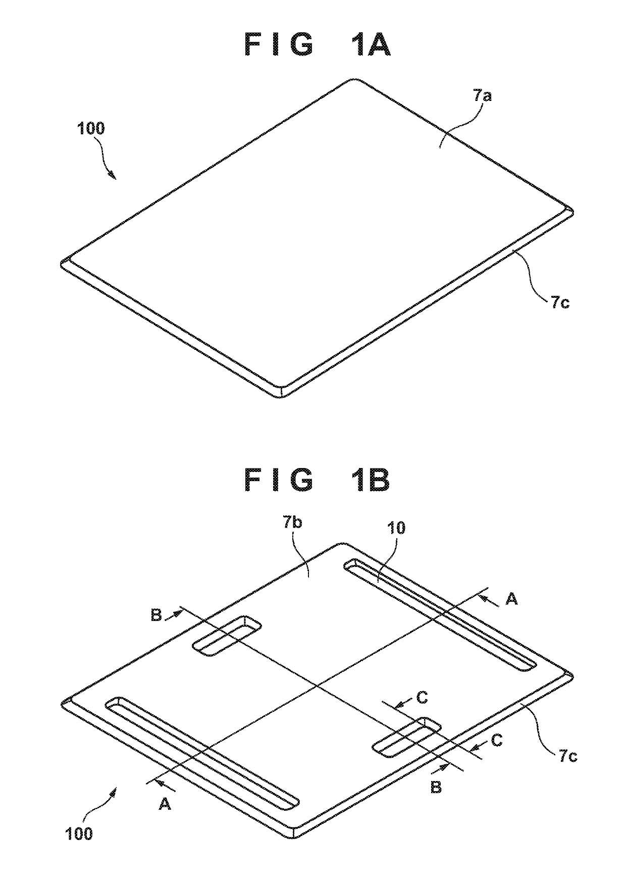
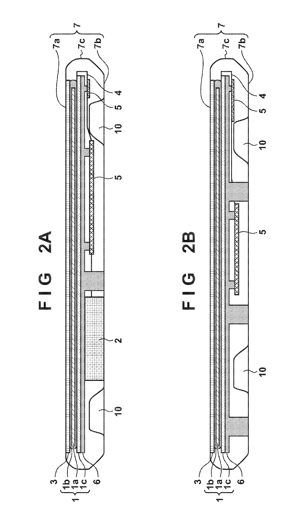
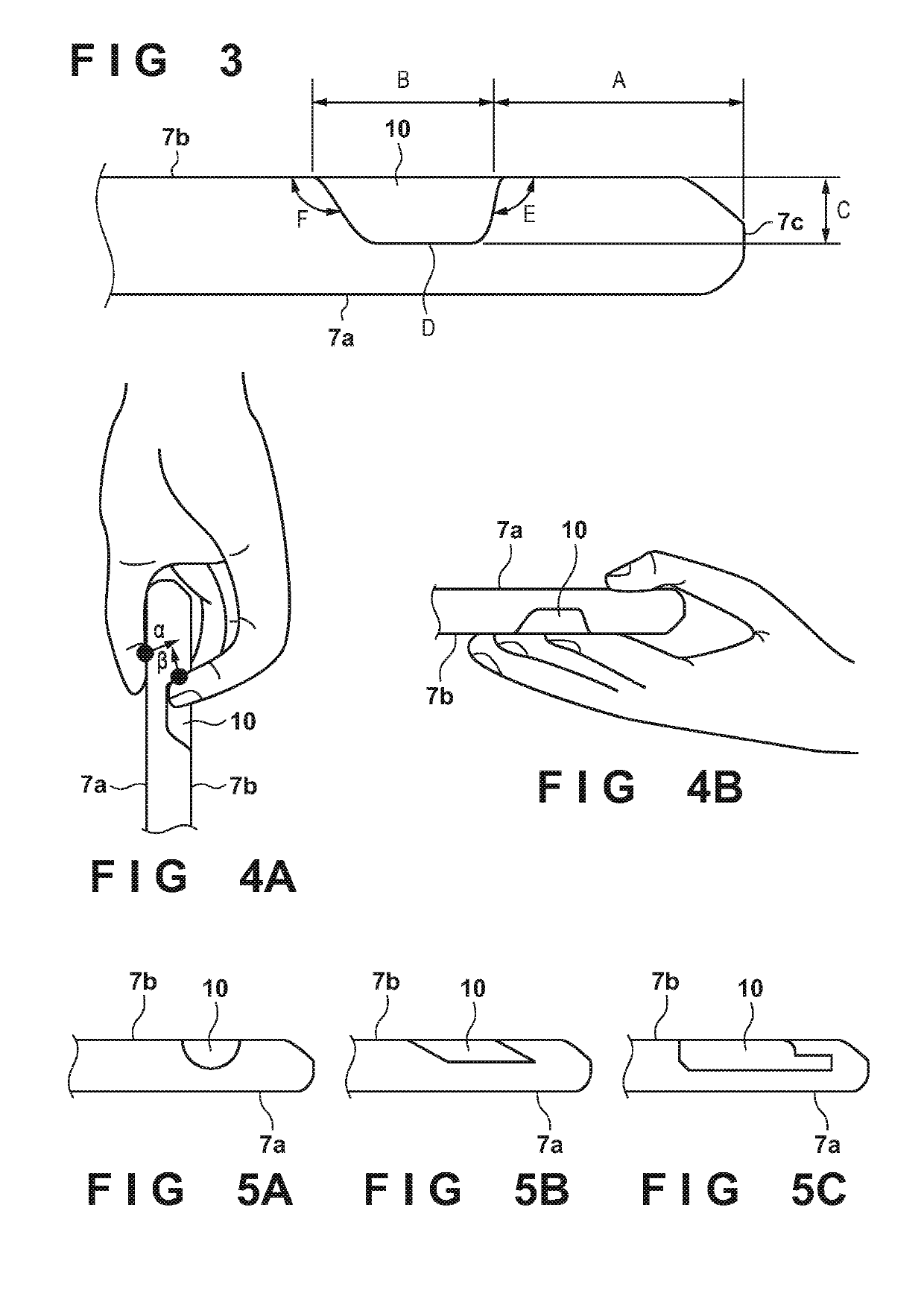
[0023]FIG. 1A shows the outer appearance of a radiation imaging apparatus (imaging apparatus) 100 including a radiation detection panel 1 when viewed from a front surface 7a and some of side surfaces 7c of a housing 7 having a cuboid shape that radiation enters. FIG. 1B is a perspective view showing a back surface 7b and some of the side surfaces 7c of the imaging apparatus 100 on the opposite side of FIG. 1A. As shown in FIG. 1B, concave grip portions 10 are formed on the back surface 7b of the housing 7 in the imaging apparatus 100 of the first embodiment. FIG. 2A is a sectional view showing the internal arrangement of the imaging apparatus 100 in an A-A direction of FIG. 1B. FIG. 2B is a sectional view showing the internal arrangement of the imaging apparatus 100 in a B-B direction of FIG. 1B. In general, the radiation of the imaging apparatus 100 is emitted by a radiation source 210 shown in FIG. 11, and the radiation detection panel 1 detects the radiation transmitted through a...

second embodiment

[0039]In the first embodiment, the compact imaging apparatus having the good gripping performance according to one embodiment has been described. In the second embodiment, in order to improve portability of an imaging apparatus, an attempt is made to reduce the weight of the apparatus, in addition to making it easier to grip. FIG. 8 is a view showing an imaging apparatus 100 when viewed from an opposite side to a radiation incident direction according to the second embodiment. At least some of grip portions 10 of the second embodiment have, for example, the same shape as the grip portions 10 of the first embodiment. No moment is produced when the imaging apparatus 100 is gripped by inserting fingers into the centers of a spacing between a pair of sides of a back surface 7b including the grip portions 10 on either side, making it possible to grip the imaging apparatus 100 stably. In the second embodiment, the centers of the grip portions 10 can be detected by tactile perception even ...


PUM

PropertyMeasurementUnit
depthaaaaaaaaaa
depthaaaaaaaaaa
thicknessaaaaaaaaaa

Abstract

A radiation imaging apparatus is provided. The apparatus includes a radiation detection panel, a housing of a cuboid shape that accommodates the radiation detection panel. The housing has a front surface that the radiation enters, a rectangular back surface arranged on a side opposite to a side of the front surface, and four side surfaces configured to connect the front surface and the back surface. The apparatus further includes a grip portion which is concave toward the radiation detection panel, formed in a peripheral region on the back surface. The grip portion has at least one of a depth not less than one-half a distance between the front surface and the back surface, and a depth not less than a distance between the back surface and a center of gravity of the radiation imaging apparatus.

Description

BACKGROUND OF THE INVENTION[0001]Field of the Invention[0002]The present invention relates to a radiation imaging apparatus and a radiation imaging system.[0003]Description of the Related Art[0004]A radiation imaging apparatus which obtains a radiation image of a target object by irradiating the target object with radiation and detecting an intensity distribution of the radiation transmitted through the target object is generally utilized in the field of an industrial non-destructive inspection or a medical diagnosis. In recent years, an imaging apparatus having a radiation detection panel which captures a digital radiation image is developed, making it possible to obtain an output image immediately.[0005]In order to allow such an imaging apparatus to image a part quickly and widely, a thin and lightweight portable imaging apparatus, that is, an electronic cassette is developed. Particularly, in recent years, a wireless imaging apparatus free from cable connection is developed in or...

Claims


Application Information

Patent Timeline
Patent Type & Authority Patents(United States)
IPC IPC(8): H01J31/50G01T1/20G03B42/02A61B6/00G01N23/04
CPCG01T1/2018A61B6/4283G01N23/04G03B42/02A61B6/566A61B6/4216A61B6/4405A61B6/42A61B6/44A61B6/4429G01T1/2006
Inventor SUZUKI, MASATAKA
Owner CANON KK
Why Eureka
Try Eureka