Window film anchoring device

a technology for anchoring devices and windows, applied in the field of window structures, can solve problems such as inability to resist lateral motion, and achieve the effect of preventing lateral motion of the free film portion and increasing the impact resistance of the film

Active Publication Date: 2007-09-13
SORAG
View PDF7 Cites 5 Cited by
  • Summary
  • Abstract
  • Description
  • Claims
  • Application Information

AI Technical Summary

Benefits of technology

[0015]The present invention is a novel window film anchoring device which comprises interlocking upper and lower engagement members. A thin polymeric film, e.g. a polyester film, having a thickness of at least 200 microns and being transparent, translucent, or being treated with ultraviolet, visible light, infrared, or radio wave filtering properties (hereinafter a “window film”) is applied to the inner surface of a window pane, to increase the impact resistance thereof. The “inner surface” is defined herein as the surface facing the room being illuminated by the light propagating through the pane, and the “outer surface” is the window pane surface facing the exterior of the room. The length of the window film is greater than that of the window pane such that a portion of the window film extends from the corresponding pane edge (hereinafter the “free film portion”). Lateral motion of the free film portion is prevented when the latter is positioned between the upper and lower engagement members. “Lateral motion” is defined herein as movement of the free film portion in a direction that would result in its being dislodged from the anchoring device.

Problems solved by technology

However, when the window pane is subjected to a sufficiently high impact that causes the pane to bend and to pull the window film in the lateral direction, the force applied by said element is unable to resist lateral motion and the window pane is separated from the frame in which it is mounted.

Method used


Image

  • Window film anchoring device
  • Window film anchoring device
  • Window film anchoring device

Examples


example 1

[0074]The strength of a window pane provided with a window film and anchoring device of the present invention was tested when subjected to an air pressure differential between the inner and outer surfaces thereof.

[0075]The testing was conducted by Architectural Testing, Inc. at its test facility in Southlake, Tex,. U.S.A. A monolithic glass having a thickness of ¼″, an overall width of 36-¼″, an overall height of 62″, and a glass opening size of 32-½″×58-½″ was drop glazed with a wedge gasket on the interior and exterior of the glass. The window was of an aluminum fixed commercial type. The frame finish was anodized and the frame corners were attached with two ¼″×1″ hex head bolts. The window units were installed with two ¼″×4″ lag bolts located 11″ from each other at the head and sill, and in the jambs at 6″ from each end and 16″ on center thereafter.

[0076]Three window units were tested in accordance with the ASTM E 330-97el standard entitled “Test Method for Structural Performance...

example 2

[0079]The blast resistance of a window pane provided with a window film and anchoring device of the present invention was tested.

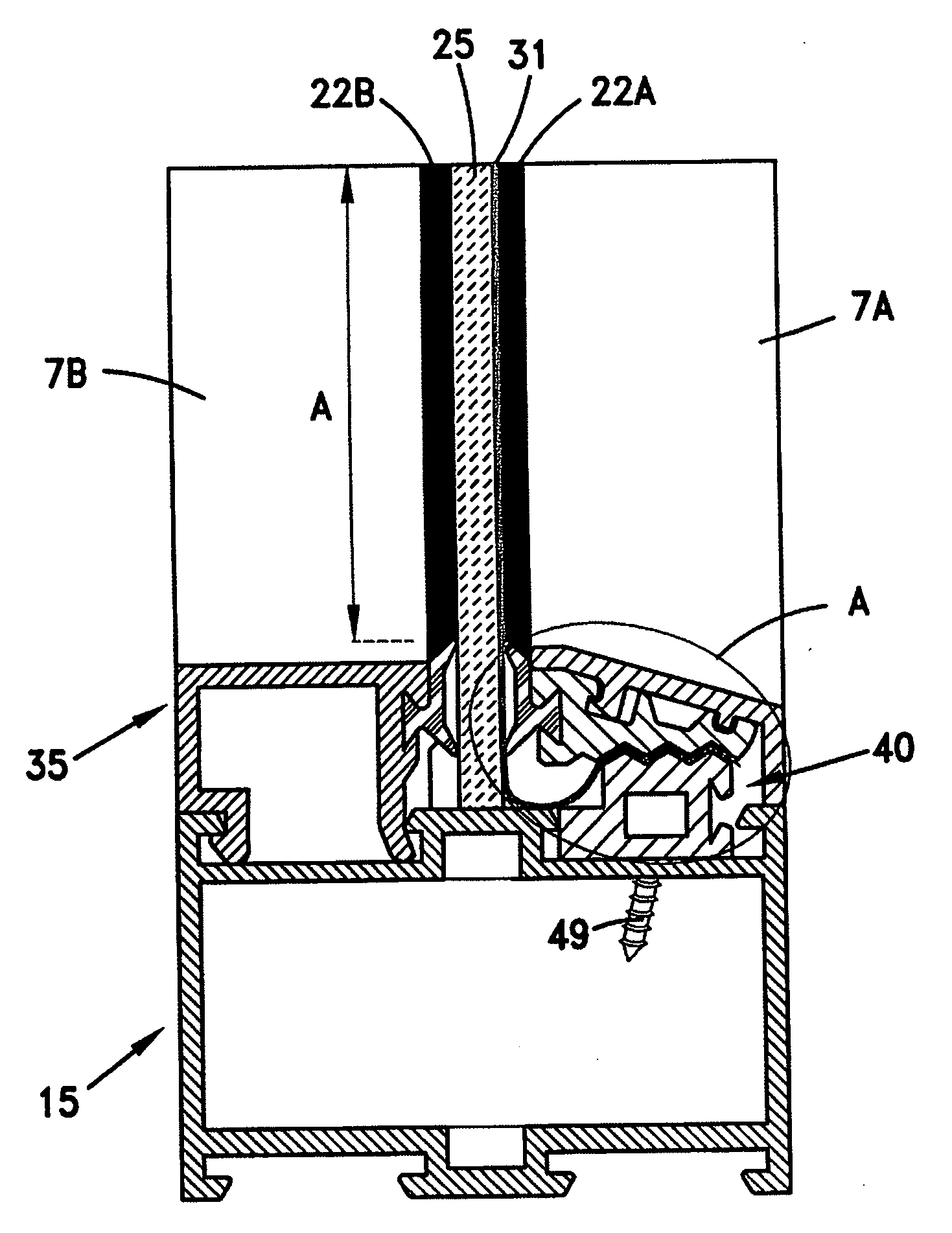
[0080]Each pane made of annealed glass and having a thickness of 6 mm was surrounded by a commercially available aluminum frame, which was enclosed in a concrete reaction structure. A 12-mil clear SafetyZone film, manufactured by Hanita Coatings RCA Ltd., Israel, was applied onto the inner surface of the pane. Two sides of the window film were anchored such that each free film portion was inserted between the engagement members of a corresponding anchoring device as shown in FIG. 9 of the present invention.

[0081]The testing was conducted by the Israeli Defense Force (IDF) and the Israeli Foreign Ministry (IFM). Impulse sensors were affixed to the reaction structure. Pressure sensors were affixed to the inner surface of the pane, in order to detect the initial impact. Various window panes were exposed to test charges of TNT. As the blast wave propagated, a ...


PUM


Abstract

A window film anchoring device is disclosed which comprises a first engagement member and a second engagement member between which a free film portion of a film affixed to a window pane is inserted. The first and second engagement members are attached to a corresponding window frame portion, and film engaging surfaces of the first engagement member are in interlocking and lateral motion preventing relation with complementary film engaging surfaces of the second engagement member so as to maintain a constant pressing force on the free film portion. The anchoring device is adapted to be a retrofit kit, and is able to be easily attached to an existing window frame, in order to increase the impact or impulse resistance of the window pane. The anchoring device may also be factory assembled to a newly produced frame.

Description

FIELD OF THE INVENTION[0001]The present invention relates to the field of window structures. More particularly, the invention relates to an anchoring device for window film, which is adapted to prevent the separation of a window pane from its frame.BACKGROUND OF THE INVENTION[0002]It is well known to employ window film consisting of a thin polymeric film, particularly a polyester film, which is applied to the inside surface of a window pane, to increase the impact resistance thereof. The window film also holds broken glass fragments together when a glass sheet is broken by an impact, such as an accidentally caused impact, e.g. initiated by physical activity, a deliberately caused impact, e.g. as a result of a break-in attempt or a bomb explosion, or a natural phenomenon, e.g. a hurricane or an earthquake.[0003]The window film is generally applied to the visible portion of the pane, and therefore the edge portions of the pane which are concealed by the window frame are not protected....

Claims


Application Information

Patent Timeline
Patent Type & Authority Applications(United States)
IPC IPC(8): E06B1/04
CPCE06B5/10
Inventor PAZ, EREZ
Owner SORAG
Why Eureka
Try Eureka