Coupling mechanism for a drive train of a hair cutting appliance

a technology of coupling linkage and hair cutting, which is applied in the direction of metal working devices, etc., can solve the problems of reducing the efficiency of common electric razors are not particularly suited for cutting hair, and reducing the efficiency of shaving all but the shortest and stiffest of hairs, etc., to achieve advanced contour following, enhance the operating performance of the appliance, and facilitate the effect of us

Active Publication Date: 2019-05-07
KONINKLJIJKE PHILIPS NV
View PDF21 Cites 5 Cited by
  • Summary
  • Abstract
  • Description
  • Claims
  • Application Information

AI Technical Summary

Benefits of technology

[0014]It is an object of the present disclosure to provide a drive train, particularly a coupling linkage for a drive train of a hair cutting appliance that may enhance the operating performance of the appliance and contributes to a pleasant user experience. Furthermore, it is desired to provide a hair cutting appliance fitted with a respective drive train. It is particularly desired that the hair cutting appliance enables both shaving and trimming operations. Even more particularly, it is desired that the cutting appliance exhibits an advanced contour following capability. Preferably, the present disclosure may generally address at least some drawbacks inherent in known prior art hair cutting appliances as discussed above, for instance. It may be further desirable to provide a drive train that is particularly suited for angular offset compensation. It would be further preferred to diminish unpleasant emissions that may emerge from a drive train, e.g. running noises and vibrations.
[0022]This aspect is based on the insight that the coupling linkage may provide the drive train with the ability to span angular and / or parallel offsets between the driving shaft and the output shaft. More particularly, a hair cutting appliance fitted with the coupling linkage may be configured to make use of a housing that comprises a neck portion that is inclined with respect to a base portion or gripping portion thereof. This may significantly improve the visibleness of the appliance during operation, particularly when shaving. Consequently, handling the device may be improved. Furthermore, the coupling linkage may be provided with the ability to compensate angular deviations. Angular deviations may involve constant deviations but also variable deviations. This may be beneficial since in this way the drive train may become considerably tolerant to angular deviations between the driving shaft and the output shaft. This may reduce the need of providing high precision parts for the drive train and the housing of the hair cutting appliance. Consequently, manufacturing the drive train and the hair cutting appliance may be simplified.
[0024]In one embodiment, the first driveable coupling element at the first end of the transmission shaft is arranged as an axially extending recess comprising an internal polygonal profile, and wherein the first driving coupling element is arranged as a substantially axially extending external polygonal profile. Consequently, the driving coupling element and the driveable coupling element may be engaged basically without significant (circumferential) backlash or backlash-free.
[0026]In one embodiment, the coupling linkage further comprises a biasing element, particularly a spring element, wherein the biasing element is interposed between the first driveable coupling element and the first driving coupling element. The biasing element may be configured to compensate length deviations in the drive train. Since the involved components may be at least slightly preloaded, particularly axially preloaded, running noises may be further reduced.
[0029]In one embodiment, the external polygonal profile of each male connector is at least sectionally provided with spherical flanks. Consequently, the respective shafts may swivel with respect to each other, thereby altering their relative angular orientation. The spherical flanks may comprise spheric or globular surfaces that may ensure that the respective driving coupling elements and driveable coupling elements are in close contact for transmitting rotation. This may further reduce running noises. The spherical flanks may roll with respect to their counterparts upon relative angular motion between neighboring shafts.

Problems solved by technology

Common electric razors are not particularly suited for cutting hair to a desired variable length above the skin, i.e., for precise trimming operations.
But even if they did, e.g. by adding attachment spacer parts, such as spacing combs, the configuration of the foil, which typically involves a large number of small perforations, would diminish the efficient capture of all but the shortest and stiffest of hairs.
Similarly, common hair trimmers are not particularly suited for shaving, primarily because the separate cutter blades require a certain rigidity, and therefore thickness, to perform the scissor action without deforming.
Furthermore, combined shaving and trimming devices show several drawbacks since they basically require two cutting blade sets and respective drive mechanisms.
Consequently, these devices are heavier and more susceptible to wear than standard type single-purpose hair cutting appliances, and also require costly manufacturing and assembly processes.
Similarly, operating these combined devices is often experienced to be rather uncomfortable and complex.
Even in case a conventional combined shaving and trimming device comprising two separate cutting sections is utilized, handling the device and switching between different operation modes may be considered as being time-consuming and not very user-friendly.
This may pose further challenges.

Method used


Image

  • Coupling mechanism for a drive train of a hair cutting appliance
  • Coupling mechanism for a drive train of a hair cutting appliance
  • Coupling mechanism for a drive train of a hair cutting appliance

Examples


Embodiment Construction

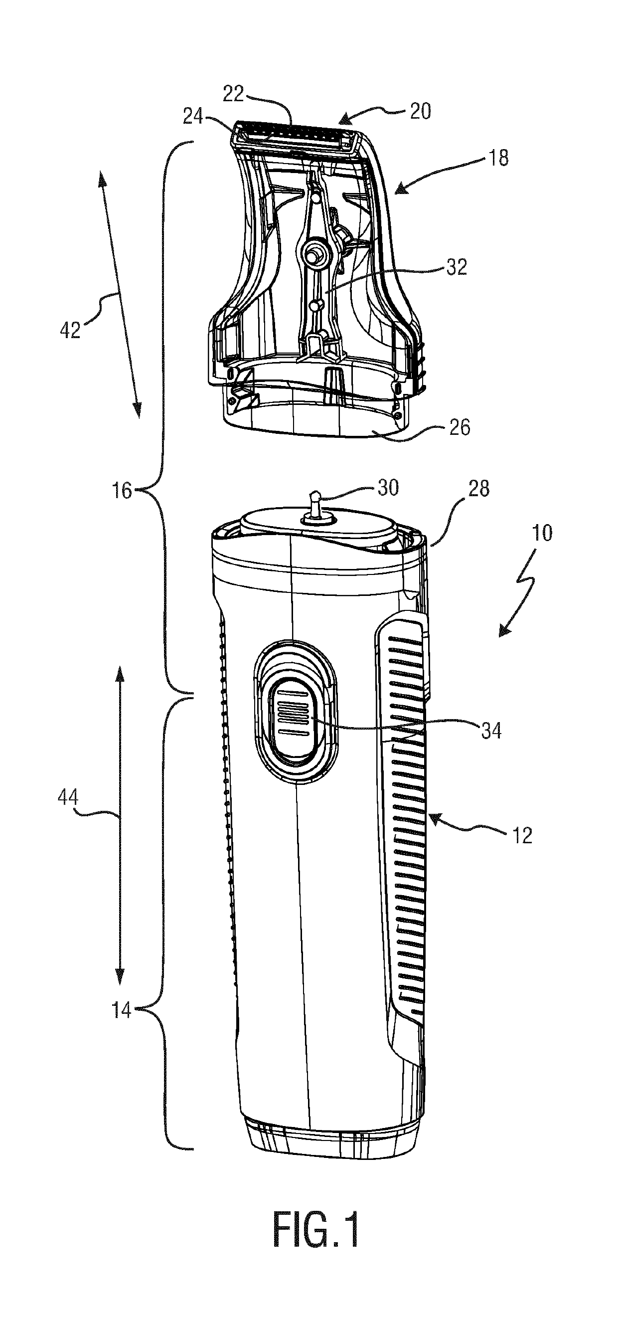
[0051]FIG. 1 shows schematically illustrates a hair cutting appliance 10, particularly an electric hair cutting appliance 10. The hair cutting appliance 10 may include a housing 12 which may house a motor for driving the hair cutting appliance 10. The housing 12 may further house a battery, such as, for instance, a rechargeable battery, a replaceable battery, etc. However, in some embodiments, the hair cutting appliance 10 may be provided with a power cable for connecting a power supply. A power supply connector may be provided in addition or in the alternative to an (internal) electric battery. The housing 12 may further comprise an operating switch 34.

[0052]The housing 12 of the hair cutting appliance 10 may generally comprise a main portion 14 and a neck portion 16. As shown in FIG. 1 in a detached state, the neck portion 16 may be associated with a cutting head 18 and, at least in some embodiments, with a receiving portion 28 for the cutting head 18 at the housing 12.

[0053]The c...


PUM


Abstract

The present invention relates to a drive train (50) of a hair cutting appliance (10) and to a self-aligning coupling linkage (66) for a drive train (50). The coupling linkage (66) comprises a driving shaft and a non-aligning output shaft (56), said coupling linkage (66) comprising: a first driving coupling element (78) arranged to be driven by a driving shaft (54), particularly by a motor shaft, a transmission shaft (70), particularly a rigid transmission shaft (70), comprising a first drivable coupling element (80) at a first end and a second driving coupling element (86) at a second end thereof, wherein first driving coupling element (78) engages the first drivable coupling element (80) for rotatingly driving the transmission shaft (70), thereby forming a first pivoting joint (76), wherein the second driving coupling element (86) is arranged to engage a second drivable coupling element (88) of an output shaft (56), wherein the first driving coupling element (78) and the first drivable coupling element (80) define a male connector comprising an external polygonal profile (90), viewed in a cross-sectional plane perpendicular to a longitudinal axis, and a female connector comprising an internal polygonal profile (102), and wherein the external polygonal profile (90) of the male connector, viewed in a longitudinal axial section, is at least sectionally provided with convexly shaped flanks (92).

Description

[0001]This application is the U.S. National Phase application under 35 U.S.C. § 371 of International Application No. PCT / EP2015 / 058009, filed on Apr. 14, 2015, which claims the benefit of International Application No. 14165280.0 filed on Apr. 18, 2014. These applications are hereby incorporated by reference herein.FIELD OF THE INVENTION[0002]The present disclosure relates to a hair cutting appliance, particularly to an electrically operated hair cutting appliance, and more particularly to a coupling linkage mechanism for a drive train of a hair cutting appliance.BACKGROUND OF THE INVENTION[0003]WO 2013 / 150412 A1 discloses a hair cutting appliance and a corresponding blade set of a hair cutting appliance. The blade set comprises a stationary blade and a movable blade, wherein the movable blade can be reciprocatingly driven with respect to the stationary blade for cutting hair. The blade set is particularly suited for enabling both trimming and shaving operations.[0004]For the purpose...

Claims


Application Information

Patent Timeline
Patent Type & Authority Patents(United States)
IPC IPC(8): B26B19/28B26B19/38B26B19/06
CPCB26B19/28B26B19/386B26B19/063
Inventor PHOON, KIN FATTEIJKELKAMP, MARCUS FRANCISCUSDE GOEIJ, GEERT WILLEMAITINK, ALBERT JAN
Owner KONINKLJIJKE PHILIPS NV
Why Eureka
Try Eureka