Vehicle air conditioner with louver operation control

a technology of louver and air conditioner, which is applied in the direction of vessel parts, transportation and packaging, vessel construction, etc., can solve the problems of deteriorating air-conditioning performance of passengers and inability to maintain right-left temperature control

Inactive Publication Date: 2002-02-19
DENSO CORP
View PDF17 Cites 46 Cited by
  • Summary
  • Abstract
  • Description
  • Claims
  • Application Information

AI Technical Summary

Problems solved by technology

Thus, right-left side independent temperature control cannot be maintained.
Further, when the right and left center louvers 603, 604 are swung as described above when sunlight enters toward only one side of the vehicle, a time for which conditioned air is directly blown toward a passenger on the one side rear seat is shorter, and air-conditioning performance for the passenger is deteriorated.

Method used


Image

  • Vehicle air conditioner with louver operation control
  • Vehicle air conditioner with louver operation control
  • Vehicle air conditioner with louver operation control

Examples


first embodiment

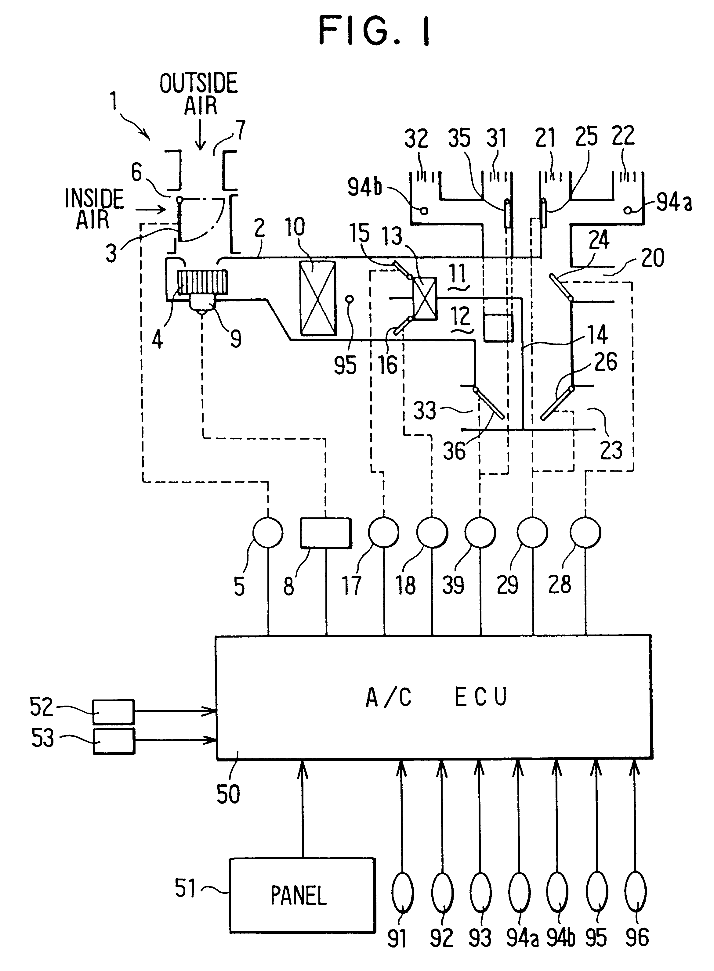
A first preferred embodiment of the present invention will be now described with reference to FIGS. 1-17. Air-conditioning equipments of an air conditioning unit 1 are controlled by an air-conditioning electronic control unit (ECU) 50, as shown in FIG. 1. In the first embodiment, the present invention is typically applied to the air conditioning unit 1 where a right-seat side air-conditioning zone (area) and a left-seat side air-conditioning zone (area) are independently temperature-controlled.

The air conditioning unit 1 includes an air conditioning duct 2 for defining an air passage. The air conditioning duct 2 is disposed at a front side of a passenger compartment of a vehicle. An inside / outside air switching door 3 and a blower 4 are disposed at an upstream air side of the air conditioning duct 2. The inside / outside air switching door 3 is driven by an actuator such as a servomotor 5 to open and close an inside air suction port 6 and an outside air suction port 7. The blower 4 is...

second embodiment

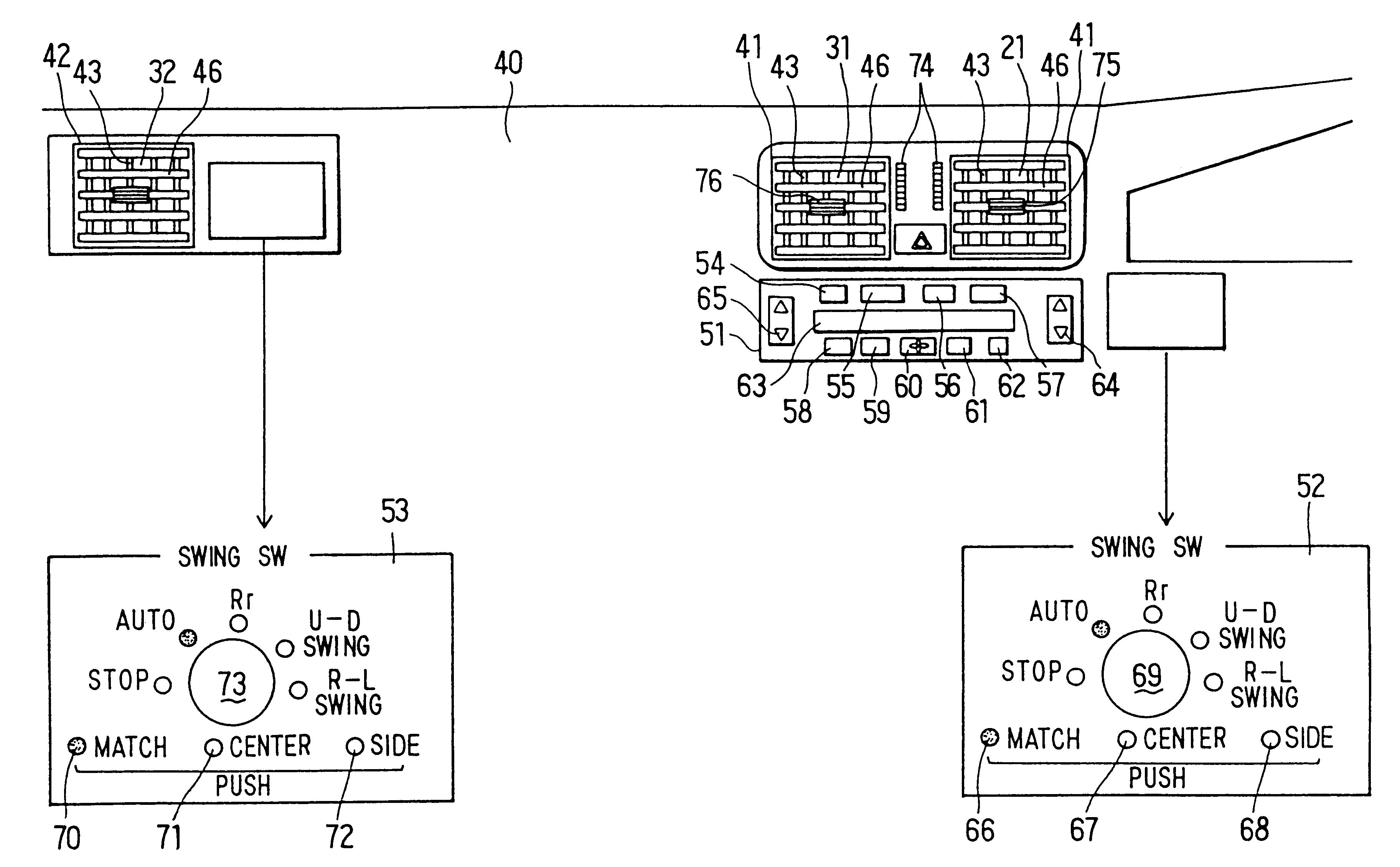
A second preferred embodiment of the present invention will be now described with reference to FIG. 18. FIG. 18 is a front view showing an air-conditioning operation panel according to the As shown in FIG. 18, a louver operation (SWING SW) panel 100 for controlling air-blowing state of conditioned air blown from the face air outlets 21, 22, 31, 32 toward the right-seat side air-conditioning zone and the left-seat side air-conditioning zone is disposed integrally with the air-conditioning operation panel 51. On the louver operation panel 100, there are provided a match switch (MATCH) 101, a right switch (Dr) 102 which is set to swing the right-seat side center and side louvers 43, 46, a left switch (Pa) 103 which is set to swing the left-seat side center and side louvers 43, 46, and a swing mode selecting switch 104.

The swing mode selecting switch 104 is a rotary type switch having selecting positions of a swing stop position (STOP), an automatic swing position (AUTO), a rear swing ...

third embodiment

As shown in FIG. 19, potentiometers 97, 98 for detecting present positions of the center and side louvers 43, 46 are connected to the air-conditioning ECU 50. In the third embodiment, plural potentiometers (e.g., four potentiometers) 97 are disposed to detect positions of louvers 43 moved in the right-left direction. As shown in FIG. 20, each of the plural potentiometers 97 includes a movable contact 97a reciprocated in the horizontal direction integrally with the link lever 44, and a resistance element 97b which changes a potential ratio by a movement of the movable contact 97a.

On the other hand, plural potentiometers (e.g., four potentiometers) 98 are disposed to detect positions of louvers 46 moved in the up-down direction. As shown in FIG. 21, each of the plural potentiometers 98 includes a movable contact 98a reciprocated in the up-down direction integrally with the link lever 47, and a resistance element 98b which changes a potential ratio by a movement of the movable contact ...


PUM


Abstract

A vehicle air conditioner includes an air conditioning unit where temperature adjustments of both right and left-seat side air-conditioning zones are independently performed. In the vehicle air conditioner, a swing range of right-seat side center louvers provided in a right center face air outlet is restricted from a front right-seat direction to a rear left-seat direction, and a swing range of left-seat side center louvers provided in a left center face air outlet is restricted from a front left-seat direction to a rear right-seat direction. Thus, right-left independent temperature control can be accurately performed in the vehicle air conditioner.

Description

1. Field of the InventionThe present invention relates to a vehicle air conditioner having an air conditioning unit in which air-blowing state to be blown toward first and second air-conditioning zones of a passenger compartment are independently controlled. More particularly, the present invention relative to a louver operation control for controlling a swing state of louvers of the vehicle air conditioner.2. Description of Related ArtIn a conventional vehicle air conditioner, as shown in FIG. 40, a right center louver 603 on a right-seat side of the vehicle and a left center louver 604 on a left-seat side of the vehicle are disposed in right and left center face air outlets 601, 602, respectively, to be swung in a horizontal direction. The right and left center louvers 603, 604 are controlled to be swung in the same direction in the horizontal direction. Further, the right center louver 603 is controlled to swing in a wide swing range from a right front seat to a left front seat, ...

Claims


Application Information

Patent Timeline
Patent Type & Authority Patents(United States)
IPC IPC(8): B60H1/34B60H1/00B60H1/24
CPCB60H1/00985B60H1/345B60H1/247B60H1/00742B60H1/00842B60H1/00871
Inventor ICHISHI, YOSHINORIKAWAI, TAKAYOSHISAMUKAWA, KATSUHIKOKAMIYA, TOSHIFUMIKAJINO, YUICHIOHGA, AKIRASUGI, HIKARU
Owner DENSO CORP
Why Eureka
Try Eureka