
Apparatus for cutting a tinted film for a vehicle window and a cutting method using the apparatus

a technology for tinted films and vehicles, applied in electrical apparatus, vehicle components, electrostatic charges, etc., can solve the problems of reducing production efficiency, removing foreign substances, and consuming tim

Active Publication Date: 2019-05-07
LEE DONGKEE
View PDF12 Cites 0 Cited by
  • Summary
  • Abstract
  • Description
  • Claims
  • Application Information

AI Technical Summary

Benefits of technology

This patent is about an apparatus and method for cutting tinted films for vehicle windows. The apparatus is designed to prevent dust and other contaminants from getting onto the film during cutting. The method allows for the continuous cutting of different types of tinted films, which can be attached to the vehicle windows, as the apparatus automatically detects the vehicle and retrieves specific cutting line data based on the vehicle's information. The apparatus can also use a liquid sprayer or static-electricity based dust absorber to prevent dust and contaminants from getting onto the film during cutting. Overall, this invention provides a more efficient and effective way to cut and attach tinted films on vehicle windows.

Problems solved by technology

There is a problem in that a long time is consumed to apply the films on many types of the glasses and the production efficiency is lowered.
However, in the above patent document, there has been a troublesome problem to remove foreign substances such as dust during the cutting operation due to the dust sticking to the film for tinting the vehicle, before cutting the film for the vehicle tinting and attaching the same to the vehicle glass.

Method used


Image

  • Apparatus for cutting a tinted film for a vehicle window and a cutting method using the apparatus
  • Apparatus for cutting a tinted film for a vehicle window and a cutting method using the apparatus
  • Apparatus for cutting a tinted film for a vehicle window and a cutting method using the apparatus

Examples


Embodiment Construction

[0026]Examples of various embodiments are illustrated and described further below. It will be understood that the description herein is not intended to limit the claims to the specific embodiments described. On the contrary, it is intended to cover alternatives, modifications, and equivalents as may be included within the spirit and scope of the present disclosure as defined by the appended claims.

[0027]It will be understood that, although the terms “first”, “second”, “third”, and so on may be used herein to describe various elements, components, regions, layers and / or sections, these elements, components, regions, layers and / or sections should not be limited by these terms. These terms are used to distinguish one element, component, region, layer or section from another element, component, region, layer or section. Thus, a first element, component, region, layer or section described below could be termed a second element, component, region, layer or section, without departing from ...


PUM


Abstract

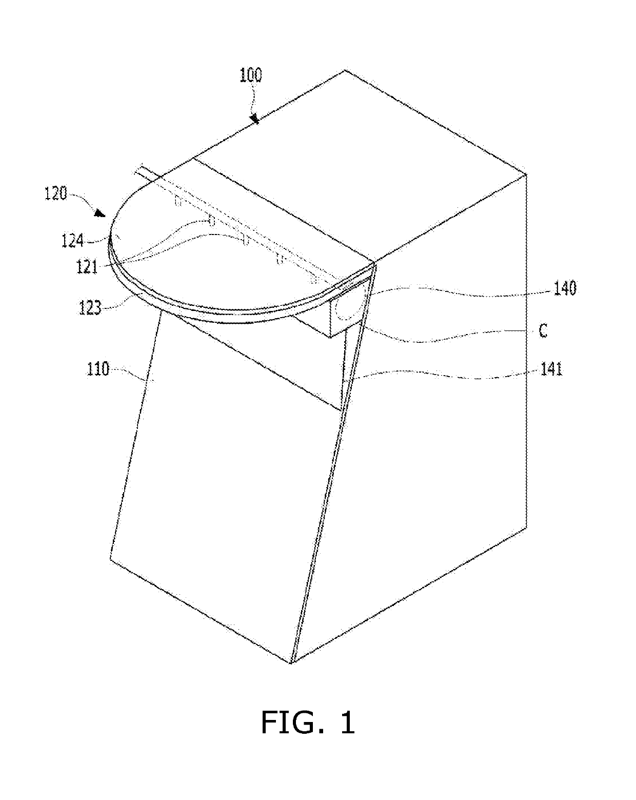
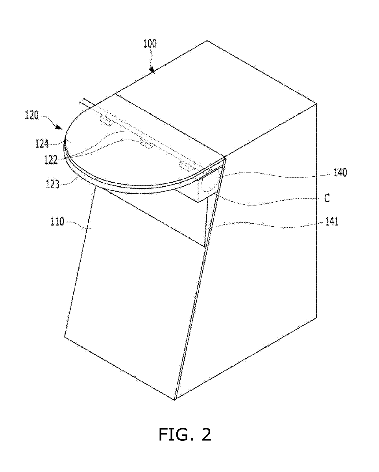
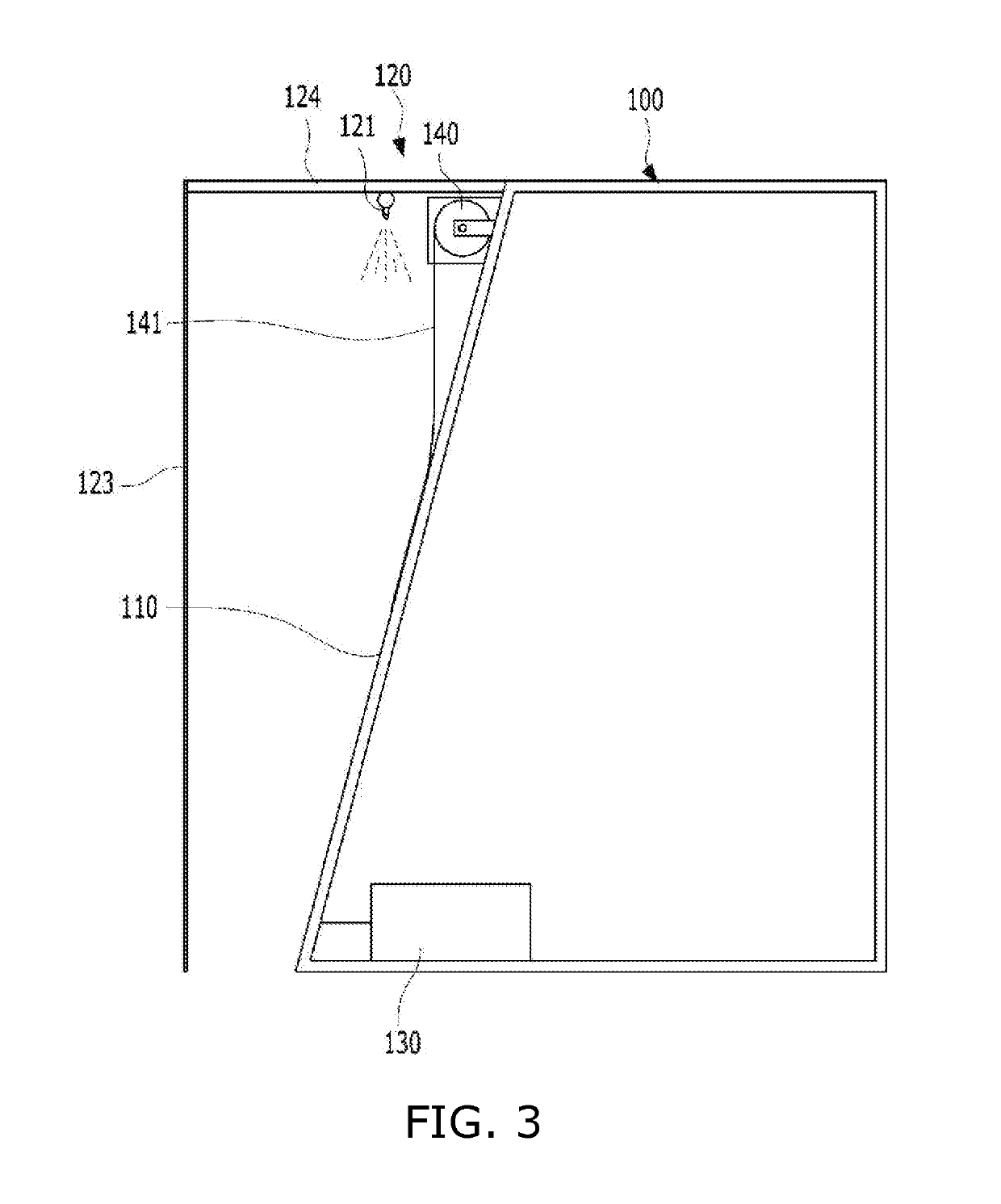
An apparatus for cutting a tinted film for a vehicle window is disclosed, the apparatus comprising: a housing having a top portion, the housing having a cutting-line displaying / displayed plate as a front portion thereof, wherein the cutting-line displaying / displayed plate is tilted such that the film is supported on the plate; a top horizontal extension from the top portion of the housing; a contaminant remover disposed on and beneath the top horizontal extension; and a cutting-line formation device housed in the housing, wherein the cutting-line formation device is configured to send cutting line data for the film to the cutting-line displaying / displayed plate when the cutting-line displaying / displayed plate includes a display panel; or the cutting-line formation device is configured to irradiate a beam corresponding to the cutting line data onto the cutting-line displaying / displayed plate when the cutting-line formation device include a beam projector.

Description

CROSS-REFERENCE TO RELATED APPLICATION[0001]This application claims the benefit of Korea patent application No. 10-2014-0146316 filed on Oct. 27, 2014, the entire content of which is incorporated herein by reference for all purposes as if fully set forth herein.BACKGROUNDField of the Present Disclosure[0002]The present disclosure relates to an apparatus for cutting a tinted film for a vehicle window and a method for cutting a tinted film for a vehicle window. More particularly, the present disclosure relates to an apparatus for cutting a tinted film for a vehicle window and a method for cutting a tinted film for a vehicle window wherein a cutting line is indicated on the tinted film using a display panel or a beam projector.Discussion of Related Art[0003]Generally, since blinds or curtains could not be installed on the rear windshield glass or door glass of automobiles, it is widely used to attach a tanning film or a light-shielding adhesive sheet.[0004]In the conventional film cutt...

Claims


Application Information

Patent Timeline
Patent Type & Authority Patents(United States)
IPC IPC(8): B62D65/06B26D7/08B26D5/00B26D7/18B26D7/01B26D7/20B26B29/06H05F1/00B60J3/00
CPCB62D65/06B26B29/06B26D5/005B26D7/01B26D7/1845B26D7/20H05F1/00B26D7/088B60J3/007B26D2005/002B26D7/28
Inventor LEE, DONGKEE
Owner LEE DONGKEE
Learn More