Flywheel intended for energy storage

Active Publication Date: 2019-05-07
ENERGIESTRO
View PDF5 Cites 2 Cited by
  • Summary
  • Abstract
  • Description
  • Claims
  • Application Information

AI Technical Summary

Benefits of technology

[0035]The fibres when they are made of glass are for example made of E-glass, a glass which has the advantage of being economic in terms of costs. In case of the use of E-glass, it is preferred to arrange an interface layer between the

Problems solved by technology

Concrete is however a material that in no way is intended to be used for a flywheel

Method used


Image

  • Flywheel intended for energy storage
  • Flywheel intended for energy storage

Examples


Embodiment Construction

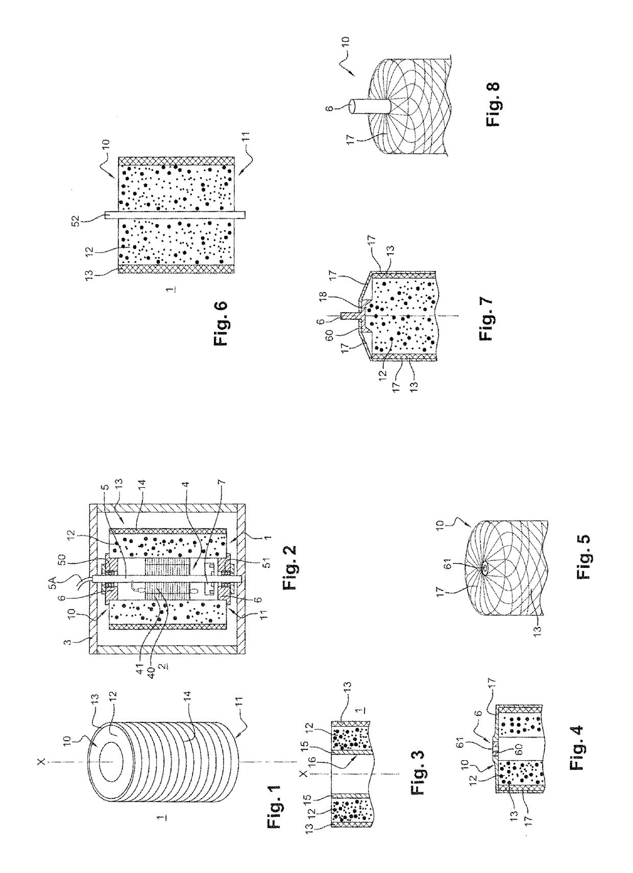
[0062]The flywheel 1 of the invention shown in FIG. 1 has a body with a cylindrical shape of longitudinal axis X.

[0063]With regards to FIG. 2, the flywheel 1 is intended to be used in an energy storage device 2.

[0064]The energy storage device 2 comprises in a closed enclosure 3, the flywheel 1, an electric / generator motor 4 which is formed of a stator 40 and of a rotor 41, with the rotor 41 being mounted on the flywheel 1 and the stator 40 on a fixed shaft 5.

[0065]The shaft 52 is hollow in order to allow for the passage of the power cables 5A of the motor.

[0066]The shaft 52 carries at each one of its ends a ball bearing, respectively denoted 50 and 51.

[0067]In the example embodiment shown in the FIGS. 1 and 2, as in the alternatives of FIGS. 3 and 4, the flywheel 1 is hollow. The shaft 5 passes centrally through and according to its length, the longitudinal body of the flywheel.

[0068]The flywheel 1 is linked by its two opposite distal ends 10 and 11 to the shaft 5, and more exactly ...


PUM

PropertyMeasurementUnit
Pressureaaaaaaaaaa
Pressureaaaaaaaaaa
Angleaaaaaaaaaa

Abstract

Disclosed is a flywheel intended for energy storage, including a cylindrical mass body including a main material with compression resistance of at least 25 MPa, such as concrete, the body being surrounded on at least one portion of the outer surface thereof with fibers, the material that makes up the fibers having a tensile strength of at least 100 Mpa. The tension of winding the fibers around the body leads to the compression of the main material, and the tension applied to the fibers is such that the stress exerted on the material of the mass body is at least equal to half of the maximum acceptable stress, the maximum stress being lower than the compression yield strength of the material that makes up the mass body, the material of the latter thus being pre-stressed.

Description

[0001]The invention relates to a flywheel intended for energy storage and its method of manufacture.[0002]The invention shall be more particularly described with regards to a flywheel manufactured according to the invention with a concrete base, without however being limited to this. The main material that makes up the flywheel will be chosen so as to be similar to a material of the concrete type in such a way as to have a low cost price and a compression resistance of at least 25 MPa.BACKGROUND OF THE INVENTION[0003]In a known manner, a flywheel via its mechanical rotation is used in a device for the temporary storage of energy that has an application in many fields, such as in the storage and the smoothing of intermittent renewable energies of the wind, solar type, the supplying of isolated sites with electricity, the restitution of energy for the braking of vehicles, etc.[0004]With regards to other devices for the storage of electrical energy such as electric batteries, the flywh...

Claims


Application Information

Patent Timeline
IPC IPC(8): F16F15/30B29C70/32H02K7/02B29L31/32
CPCF16F15/30B29C70/32H02K7/025Y02E60/16B29L2031/32
Inventor GENNESSEAUX, ANDRE
Owner ENERGIESTRO
Why Eureka
Try Eureka