
Low-glare fluorescent-powder LED light device and imaging device comprising the same

a fluorescent-powder led light and fluorescent-powder technology, which is applied in the direction of semiconductor devices, optics, instruments, etc., can solve the problems of optical capture devices failing to receive images, the color rendering of led light sources is not good, and the inability to produce ideal led light sources, etc., to confirm the consistency of images

Active Publication Date: 2019-05-21
AGIEMINDS MICRO OPTICS CO LTD
View PDF1 Cites 1 Cited by
  • Summary
  • Abstract
  • Description
  • Claims
  • Application Information

AI Technical Summary

Benefits of technology

[0012]One object of the present invention is to provide a low-glare fluorescent-powder LED light device, wherein the central light beams emitting from a high-frequency directional light source thereof do not reach the fluorescent-powder LEDs, so that the fluorescence interference of the fluorescent-powder LEDs can be avoided. Thus, the credibility of an image obtained through the high-frequency directional light source can be increased.
[0013]Another object of the present invention is to provide a low-glare fluorescent-powder LED light device, which may employ the fluorescent-powder LEDs or high-frequency LEDs thereof to illuminate a target to obtain an image. Both images respectively by using the fluorescent-powder LEDs and the high-frequency LEDs can be compared with each other to confirm the validity of the images.
[0014]A further object of the present invention is to provide a low-glare fluorescent-powder LED light device, wherein the high-frequency LEDs thereof are arranged in radial symmetry, so that a target can be illuminated with more scattering light from the high-frequency LEDs, and thus the target can be observed more easily.
[0015]A still further object of the present invention is to provide an imaging device, which includes a low-glare fluorescent-powder LED light device and a light receiving element. The fluorescent-powder LED light device includes a shell connectable with the light receiving element, so that the image of a target can be captured more accurately, and the target can be observed more easily.
[0018]Since the low-glare fluorescent-powder LED light device is designed such that, when the high-frequency directional light source is turned on, the central light beams emitting therefrom do not reach the fluorescent-powder LED, so that the fluorescence interference due to the fluorescent-powder LED subjected to the central light beams can be avoided. Furthermore, an image, which is obtained by the multi-frequency directional light source illuminating a target, can be compared with another image through the high-frequency directional light source to confirm the consistency of the images. Still furthermore, the radial symmetry design of the high-frequency directional light source allows the target to be illuminated with more scattering light. Therefore, true images without color deviation can be obtained.

Problems solved by technology

If a proper energy difference is not available, an ideal LED light source cannot be produced.
However, the color rendering of this light source is not good.
In addition, some identification equipment employs UV light as an excitation light, which cannot be directly observed with human eyes; however, for conducting a proper operation of the equipment, investigators should rely on white light illumination.
This kind of light pollution is due to face-to-face illumination, which may cause an optical capture device to fail in receiving an image, and thus is referred to as “face-to-face glare”.
However, in criminal investigation or biological research, such substantial adjustment for the contents of an image may change the image data itself.
Thus, in court offence and defense or in research publication, the credibility of the image data may be challenged, thus leading to an adverse consequence.

Method used


Image

  • Low-glare fluorescent-powder LED light device and imaging device comprising the same
  • Low-glare fluorescent-powder LED light device and imaging device comprising the same
  • Low-glare fluorescent-powder LED light device and imaging device comprising the same

Examples


first embodiment

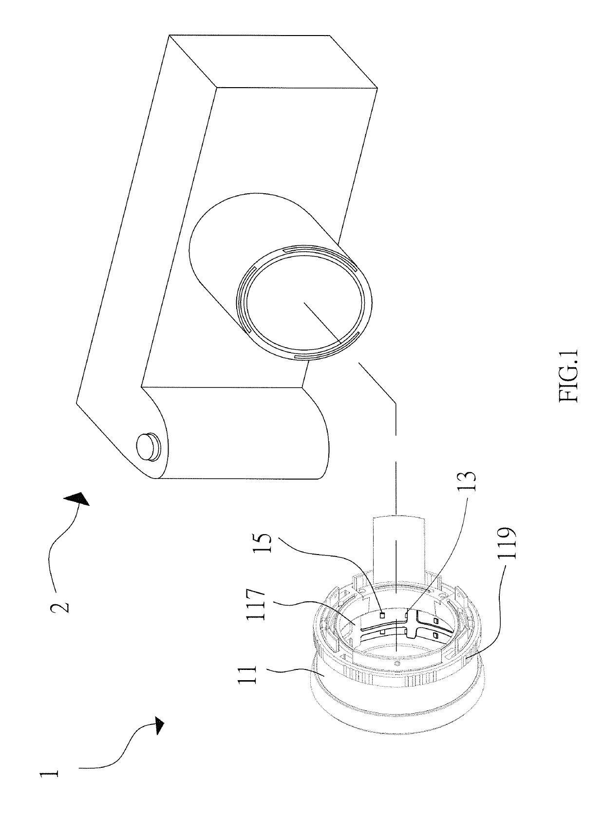
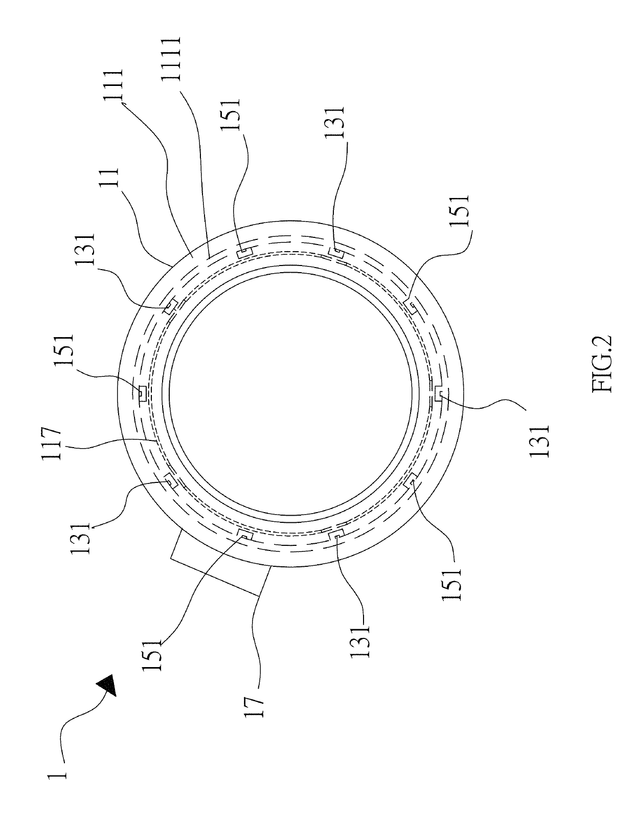
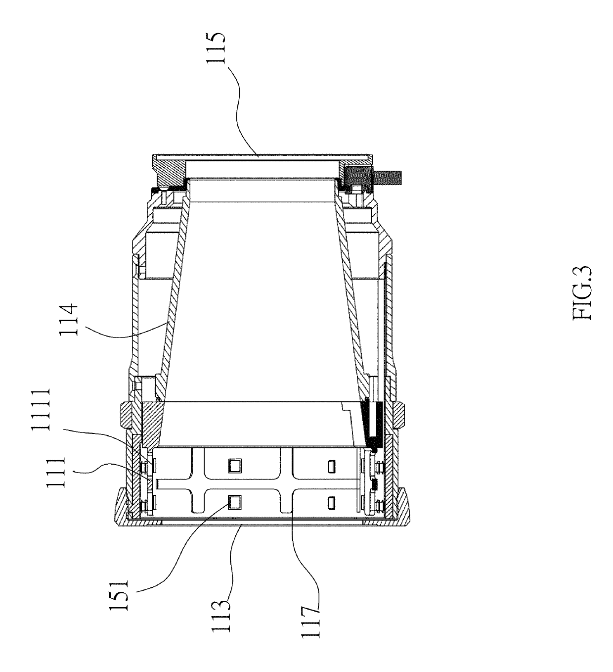
[0036]Referring to FIGS. 1 through 3, a low-glare fluorescent-powder LED light device according to the present invention is shown, which generally comprises a cylindrical shell 11, two multi-frequency directional light sources 13, two high-frequency directional light sources 15, and an electrical control circuit 17. In this embodiment, each multi-frequency directional light source includes five fluorescent-powder LEDs 131, wherein each LED is formed into a white LED package, which employs sapphire as a substrate. The substrate chip can emit blue light when the LED is enabled. The blue light can illuminate the red and green phosphors or fluorescent powders in front of the substrate chip to respectively emit red light and green light, each of which has a frequency lower than the blue light and is referred to as an excited light beam. As such, the spectrum of light emitting from each fluorescent-powder LED includes red, green and blue light, which recombines to form white light for ill...

second embodiment

[0042]FIGS. 6 and 7 show the present invention, wherein a low-glare fluorescent-powder LED light device 1′ is worked with a light receiving element 2′, which is interpreted as an ophthalmoscope. As shown, the low-glare fluorescent-powder LED light 1′ generally comprises a cylindrical shell 11′, a multi-frequency directional light source 13′, a high-frequency directional light source 15′, and an electrical control circuit 17′. The multi-frequency directional light source 13 includes a plurality of fluorescent-powder LEDs 131′, each of which is interpreted as a white LED composed of a blue-light substrate chip and a yellow phosphor or fluorescent powder. The high-frequency directional light source 15′ includes a plurality of high-frequency LEDs 151′. In a fundus examination, some injections can be used, one of which is a fluorescent dye having an excitation wavelength about 490 nm, which is different from the central frequency (about 470 nm) of the commonly used blue LED. Thus, the hi...

third embodiment

[0047]Recently, transgenic technology prevails in biological science researches. Since a transgene at a particular segment of a DNA sequence can be inserted with fluorescent protein gene, after the transgene being introduced to an organism, such as white mice, rabbits or zebrafishes, to confirm whether the transgene is successfully introduced to the organism, a high-frequency light source can be used to illuminate the organism. If fluorescence is detected, then a successful introduction of the transgene can be confirmed. FIG. 8 through 10 show the present invention, wherein the low-glare fluorescent-powder LED light device 1″ generally comprises a cubic shell 11″, a multi-frequency directional light source 13″, a high-frequency directional light source 15″, and an electrical control circuit 17″.

[0048]In this embodiment, the multi-frequency directional light source 13″ includes 8 fluorescent-powder LEDs 131″, each of which is interpreted as a white LED. The high-frequency directional...


PUM


Abstract

A low-glare fluorescent-powder LED light device includes a shell, a multi-frequency directional light source, a high-frequency directional light source, and an electrical control circuit. The shell has a surrounding wall, which defines a front opening and a rear opening and has an inner surface extending along a central axis. The multi-frequency directional light source, including at least one fluorescent-powder LED, is disposed at the inner surface of the shell. The high-frequency directional light source, including a plurality of high-frequency LEDs, is disposed at the inner surface of the shell such that the high-frequency LEDs are arranged in radial symmetry about the central axis. The electrical control circuit can drive the multi-frequency directional light source and / or the high-frequency directional light source. The central light beams emitting from the high-frequency LEDs do not reach the fluorescent-powder LED, so that the fluorescence interference of the fluorescent-powder LED can be avoided.

Description

FIELD OF THE INVENTION[0001]The present invention relates to a low-glare fluorescent-powder LED light device and an imaging device comprising the LED light device.BACKGROUND OF THE INVENTION[0002]Earlier light-emitting diodes (LEDs) are mostly monochromatic LEDs. The light emission of an LED is due to electrons falling to a lower energy level. If a proper energy difference is not available, an ideal LED light source cannot be produced. Thus, earlier technology requires red, blue, and green chips to be assembled together to form a single white LED component. For this reason, the earlier white LEDs are also called multi-chip white LEDs.[0003]Since Nichia Corporation disclosed a phosphor-LED device, which is a light-emitting diode covered with a layer of phosphor or fluorescent powder, more and more applications of LEDs has been developed. For example, a blue LED chip emits blue light passing through a material containing phosphors which fluoresce in yellow; the original blue light and...

Claims


Application Information

Patent Timeline
Patent Type & Authority Patents(United States)
IPC IPC(8): G03B15/02H01L33/50G03B15/05
CPCG03B15/02G03B2215/056G03B2215/0539H01L33/502G03B2215/0571G03B2215/0575G03B2215/0567G03B15/05
Inventor YANG, CHIH-YI
Owner AGIEMINDS MICRO OPTICS CO LTD
Learn More