
Chair

a chair and backrest technology, applied in the field of chairs, can solve the problems of insufficient support effect of the backrest of the conventional chair, inability to fully support the rear waist of the user, and discomfort of the user sitting on the conventional chair, so as to increase the comfortability of the chair

Active Publication Date: 2019-05-28
WU YAO CHUAN
View PDF62 Cites 6 Cited by
  • Summary
  • Abstract
  • Description
  • Claims
  • Application Information

AI Technical Summary

Benefits of technology

[0012]When a user sits on the chair, the back supporting structure may support the back of the user for increasing the comfortability of the chair. The waist supporting structure is pivoted to fit and abut the rear waist of the user. The waist supporting structure may sufficiently support the rear waist of the user. Therefore, the comfortability of the chair is increased by the waist supporting structure, and the waist supporting structure may avoid causing spinal diseases of the back and the waist.

Problems solved by technology

Therefore, a supporting effect of the backrest of the conventional chair is insufficient.
Thus, the user seated on the conventional chair is uncomfortable.
A space is formed between the backrest and the seat of the conventional chair, making the backrest not able to fully support the rear waist of the user, and this easily causes spinal diseases.
When the user extends the arms, the extensibility of each one of the arms is easily interfered by the top part of the backrest.

Method used


Image

  • Chair
  • Chair
  • Chair

Examples


Embodiment Construction

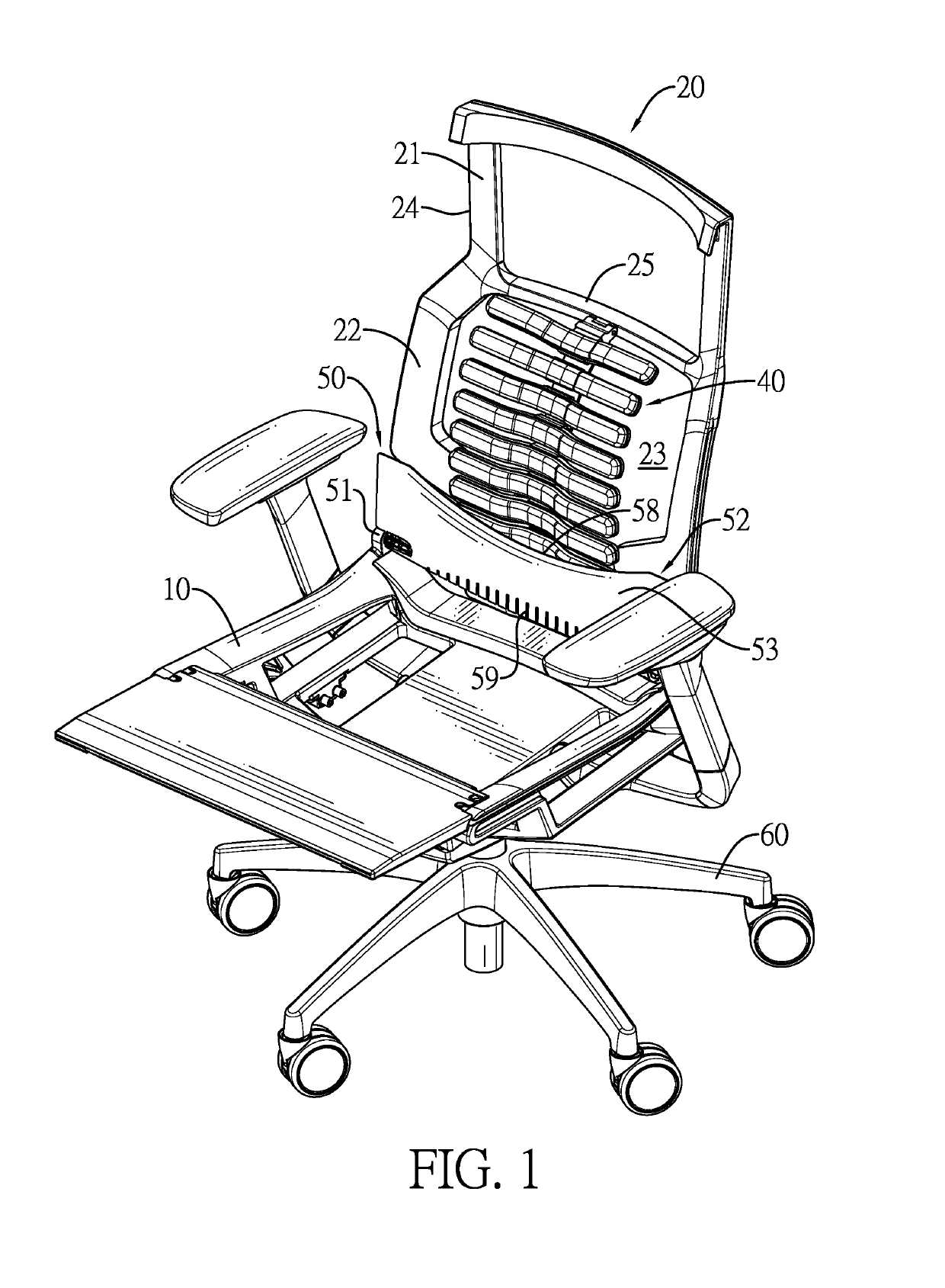
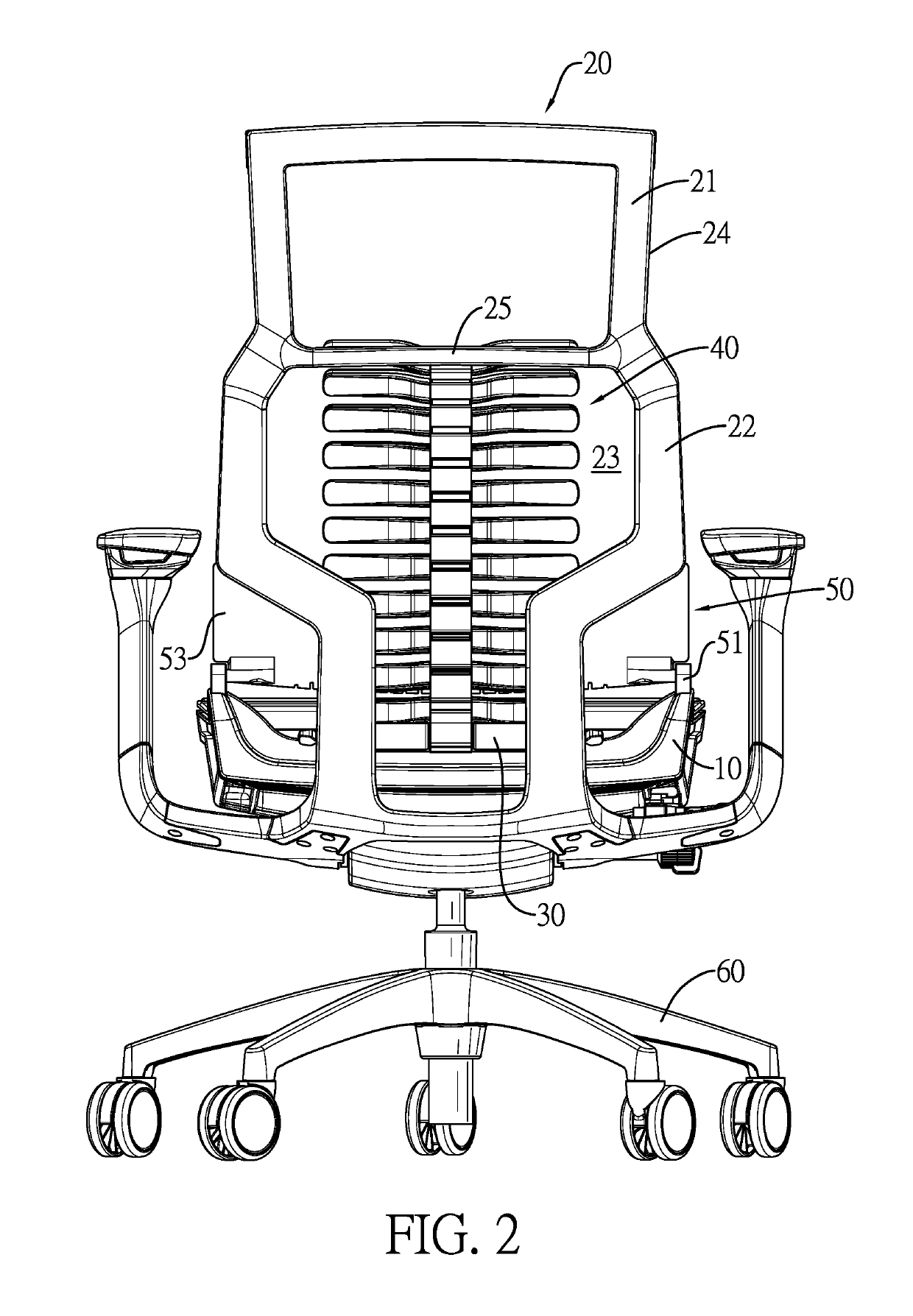
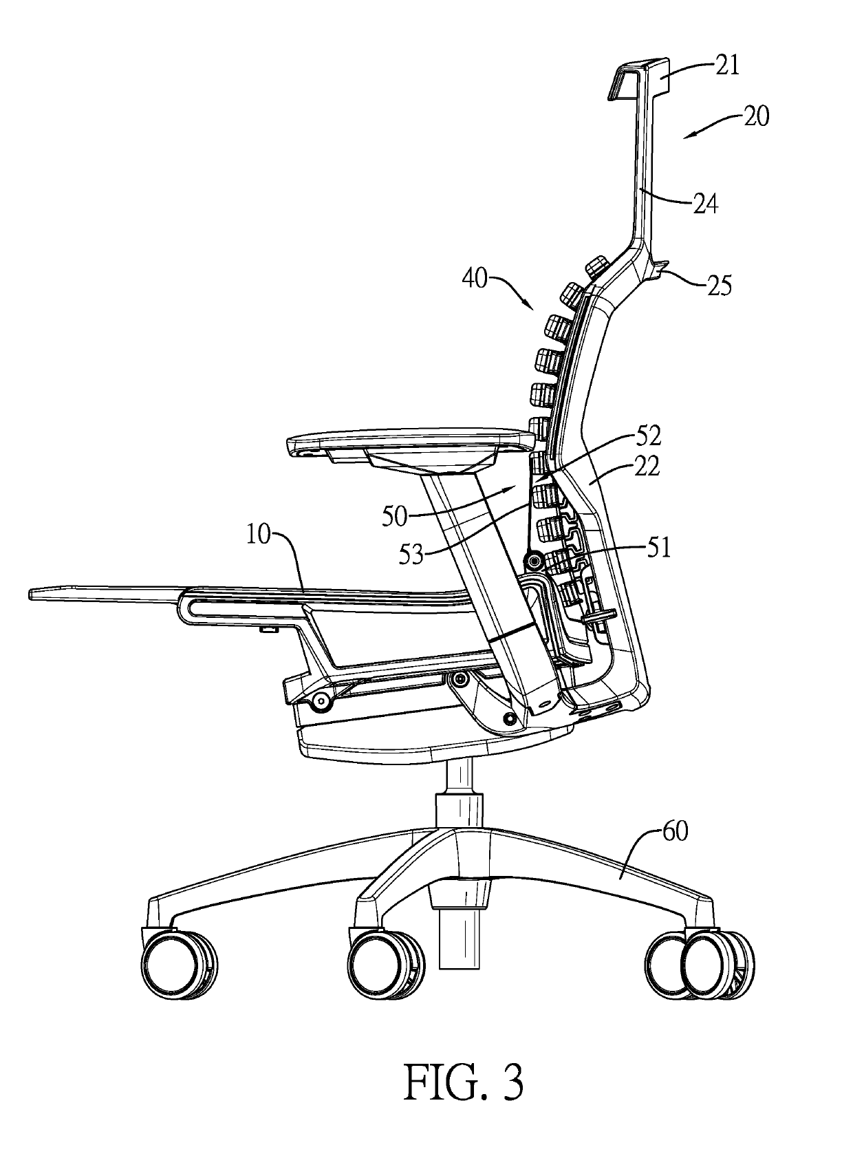
[0023]With reference to FIGS. 1 to 3, an embodiment of a chair in accordance with the present invention comprises a seat 10, a backrest 20, a lift structure 30, a back supporting structure 40, and a waist supporting structure 50. Furthermore, the chair has a leg assembly 60 deposited below the seat 10.

[0024]The backrest 20 is deposited behind a rear side of the seat 10, and has a head portion 21, a back portion 22, and a connecting rod 25. The head portion 21 is deposited above the seat 10. The back portion 22 is formed below the head portion 21 of the backrest 20, is located behind the rear side of the seat 10, and has a front surface, a bottom, and a space 23. The space 23 is formed through the back portion 22 of the backrest 20, and is located above the bottom of the back portion 22. The connecting rod 25 is formed between the head portion 21 and the back portion 22 of the backrest 20, and is located above the space 23 of the back portion 22. Furthermore, the transversal width of...


PUM


Abstract

A chair has a seat, a backrest, a lift structure, a back supporting structure, and a waist supporting structure. The backrest is deposited behind the seat. The lift structure is deposited on the backrest. The back supporting structure has a bending element and multiple supporting strips. The bending element is connected with the backrest and the lift structure, and is elastic and bendable to deform. The supporting strips are deposited on the bending element at spaced intervals from a top to a bottom of the bending element. The waist supporting structure is deposited in front of the back supporting structure. The waist supporting structure has two pivoting bases and a supporting plate. The pivoting bases are deposited on the seat. The supporting plate is pivoted between the two pivoting bases, abuts the back supporting structure, and selectively abuts the backrest.

Description

[0001]This application claims the benefits of China patent applications No. 201720284167.4 and No. 201720284595.7, both filed on Mar. 22, 2017.BACKGROUND OF THE INVENTION[0002]1. Field of the Invention[0003]The present invention relates to a chair, and more particularly to a chair that conforms to ergonomics and provides a supporting effect.[0004]2. Description of Related Art[0005]A conventional chair has a leg assembly, a seat, and a backrest. The seat is mounted on the leg assembly. The backrest is mounted behind the seat. In use, a user sits on the seat of the conventional chair, and a back of the user is supported by the backrest of the conventional chair for resting. The backrest is a plate and cannot deform to fit different body shapes of users. Therefore, a supporting effect of the backrest of the conventional chair is insufficient. The backrest may not conform to ergonomics. Thus, the user seated on the conventional chair is uncomfortable. A space is formed between the backr...

Claims


Application Information

Patent Timeline
Patent Type & Authority Patents(United States)
IPC IPC(8): A47C7/40A47C7/38A47C7/00A47C3/20A47C7/46A47C1/032A47C7/44
CPCA47C7/402A47C3/20A47C7/004A47C7/38A47C7/40A47C7/46A47C1/03255A47C1/03266A47C7/44
Inventor WU, YAO-CHUAN
Owner WU YAO CHUAN
Learn More