Electric brake device

a technology of brake device and electric brake, which is applied in the direction of brake system, mechanical equipment, transportation and packaging, etc., can solve the problems of deteriorating fuel or electric power efficiency of the vehicle, affecting the comfort of the vehicle, and loud operating noise, so as to reduce the generation of operating nois

Active Publication Date: 2016-06-23
NTN CORP
View PDF5 Cites 7 Cited by
  • Summary
  • Abstract
  • Description
  • Claims
  • Application Information

AI Technical Summary

Benefits of technology

[0015]An object of the present invention is to provide an electric brake device that

Problems solved by technology

In a case where the electric brake device described above in patent document 1 or 2 is mounted to a vehicle, comfortability in the vehicle may be impaired due to an operating noise of the electric brake device.
In many cases, a principal factor of generation of a loud operating noise in the electric brake device is a noise generated in a power transmission mechanism such as a gear when a motor rotates at a high speed.
In a friction brake that operates so as to press a brake pad against a disc rotor, even when a pressing force of the brake pad has become zero, a frictional force causing a drag torque is generated

Method used


Image

  • Electric brake device
  • Electric brake device
  • Electric brake device

Examples


Embodiment Construction

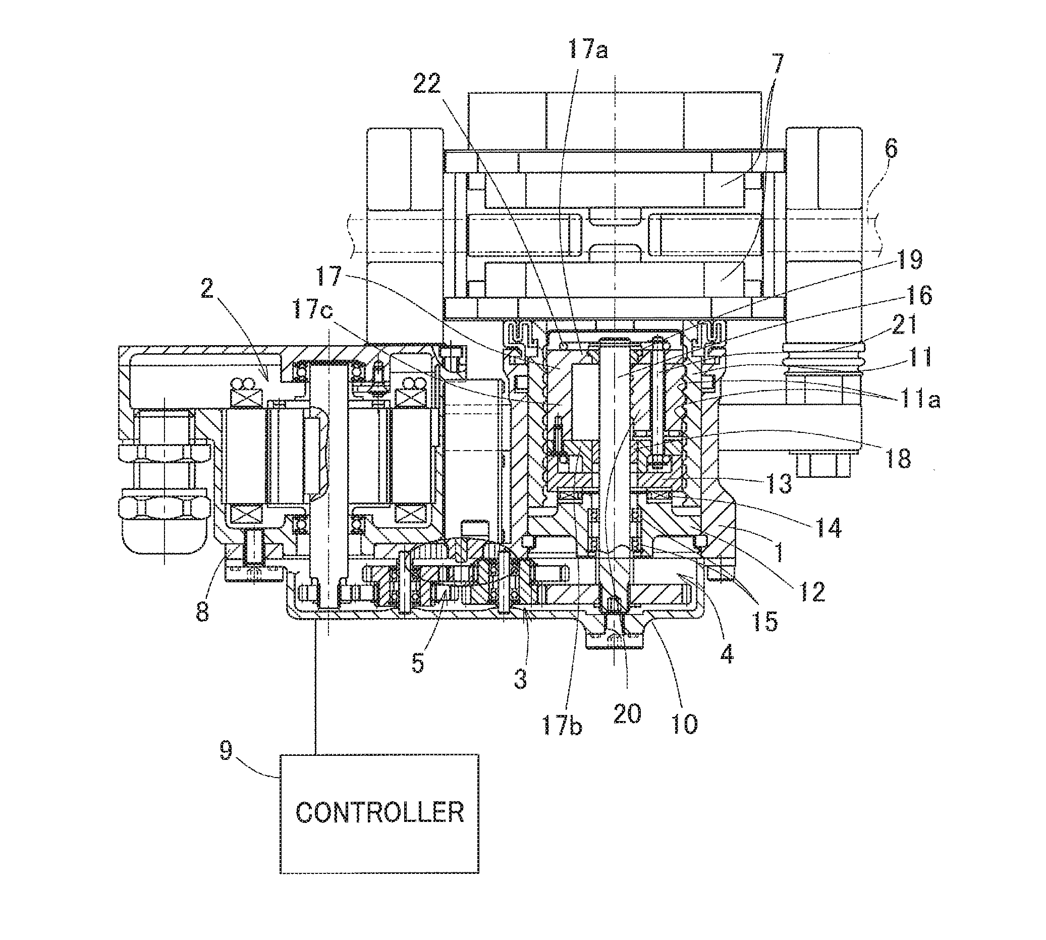
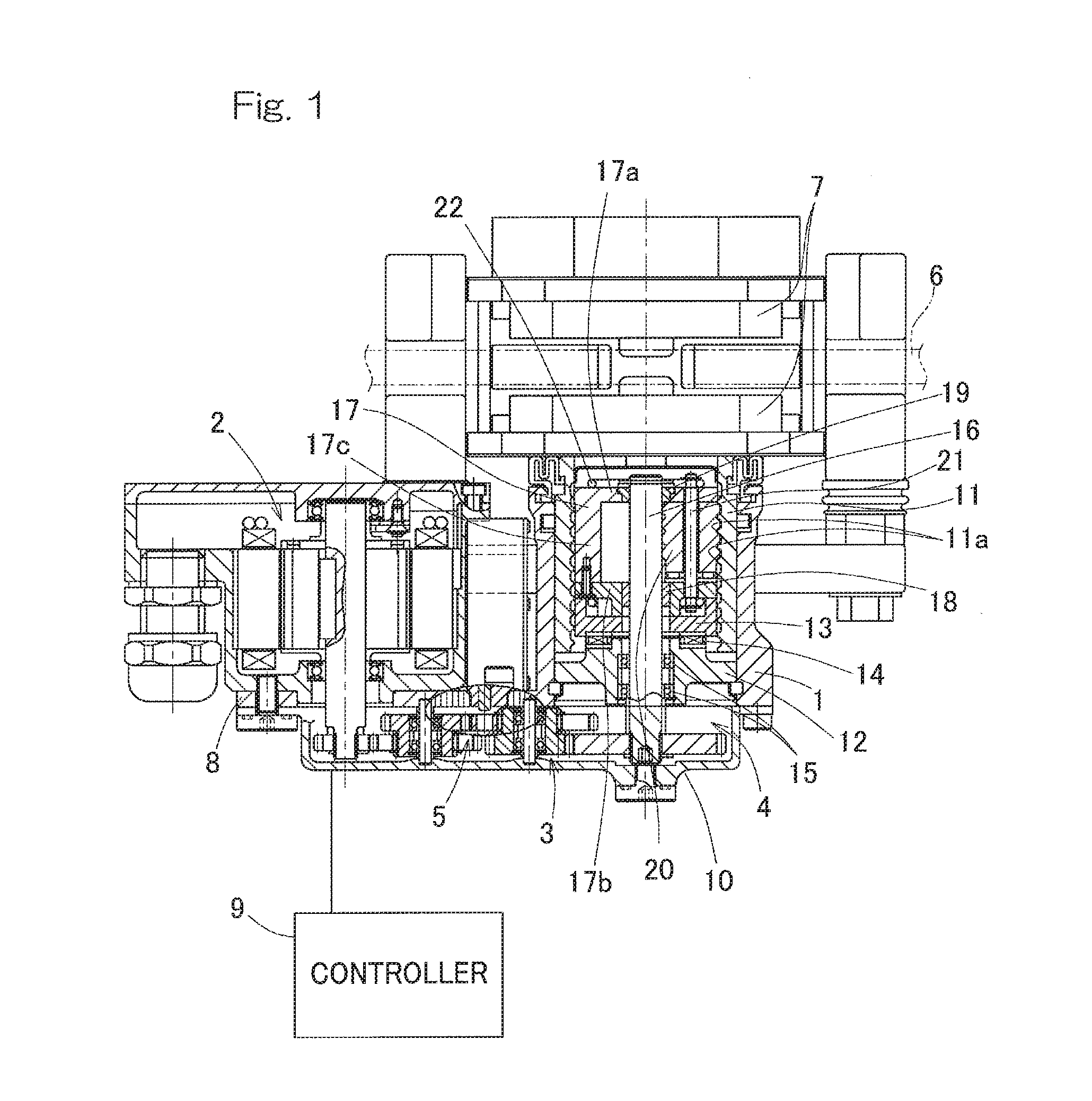
[0034]An electric brake device according to a first embodiment of the present invention will be described with reference to FIGS. 1 to 5. As shown in FIG. 1, the electric brake device includes: a housing 1; an electric motor 2; a speed reduction mechanism 3 configured to reduce a speed of rotation of the electric motor 2; a linear motion mechanism 4; a locking mechanism 5; a brake rotor 6; a brake pad 7, and a controller 9 (FIG. 3). A base plate 8 is provided at an opening end of the housing 1 so as to extend radially outward, and the electric motor 2 is supported by the base plate 8. The linear motion mechanism 4 is incorporated into the housing 1 so as to apply a braking force to the brake rotor 6, in this example, to a disc rotor 6 by output from the electric motor 2. The opening end of the housing 1 and an outer side surface of the base plate 8 are covered by a cover 10.

[0035]The linear motion mechanism 4 will be described. The linear motion mechanism 4 is a mechanism that conve...


PUM


Abstract

An electric brake device that allows reduction of generation of an operating noise without impairing a function of a brake, is provided. The electric brake device includes a brake rotor, a brake pad, an electric motor, a linear motion mechanism, and a controller. The controller includes: a motor angular velocity control section configured to control an angular velocity of the electric motor; differential value calculator configured to calculate a differential value of a braking command value; and angular-velocity-corresponding-to-differential-value limiting section configured to limit the angular velocity of the electric motor by the motor angular velocity control section such that the less the differential value calculated by the differential value calculator is, the lower the angular velocity of the electric motor is.

Description

CROSS REFERENCE TO THE RELATED APPLICATION[0001]This application is a continuation application, under 35 U.S.C. §111(a), of international application No. PCT / JP2014 / 072909, filed Sep. 1, 2014, which is based on and claims Convention priority to Japanese patent application No. 2013-186047, filed Sep. 9, 2013, the entire disclosure of which is herein incorporated by reference as a part of this application.BACKGROUND OF THE INVENTION[0002]1. Field of the Invention[0003]The present invention relates to electric brake devices that convert a rotary motion of electric motors into a linear motion through linear motion mechanisms, and press brake pads against disc rotors.[0004]2 Description of Related Art[0005]To date, the following brakes have been proposed as electric brakes or friction brakes.[0006]1. An actuator that converts a rotary motion of a motor into a linear motion through a linear motion mechanism by stepping on a brake pedal, and presses a brake pad against a brake disc, thereb...

Claims


Application Information

Patent Timeline
IPC IPC(8): F16D65/18F16D55/225
CPCF16D65/18F16D55/225F16D2125/48F16D2125/40F16D2125/52F16D2121/24B60T13/741
Inventor MASUDA, YUI
Owner NTN CORP
Why Eureka
Try Eureka