
Damping force control apparatus

a technology of control apparatus and force, which is applied in the direction of bicycle equipment, transportation and packaging, instruments, etc., can solve problems such as degrading durability, and achieve the effect of improving ride comfort and riding comfor

Active Publication Date: 2012-11-27
TOYOTA JIDOSHA KK
View PDF21 Cites 7 Cited by
  • Summary
  • Abstract
  • Description
  • Claims
  • Application Information

AI Technical Summary

Benefits of technology

The present invention provides a damping force control apparatus for suspension systems that can improve riding comfort of vehicles by controlling the damping force characteristic of dampers based on the vibration state of the sprung member. The apparatus includes a sensor for obtaining the sprung-member-unsprung-member-relative-speed, which is a measure of the vibration speed of each suspension apparatus. The apparatus uses a control theory to determine the required damping force and changes the damping force characteristic of each damper accordingly. This allows for a more comfortable ride when the vehicle is subjected to vibrations in the middle / high frequency range. The apparatus also includes a damping force characteristic control means for changing the damping force characteristic of each damper based on the vibration state of the sprung member, and an operation prohibiting means for preventing the operation of the damping force characteristic changing means when the vehicle is subjected to vibrations in the middle / high frequency range. The invention aims to improve the riding comfort of vehicles without increasing the operation frequency or amount of the damping force characteristic changing means.

Problems solved by technology

The increase in the operation frequency of or in the operation amount of the damping force characteristic changing means may degrade its durability.

Method used


Image

  • Damping force control apparatus
  • Damping force control apparatus
  • Damping force control apparatus

Examples


Embodiment Construction

[0041]An embodiment of the present invention will next be described.

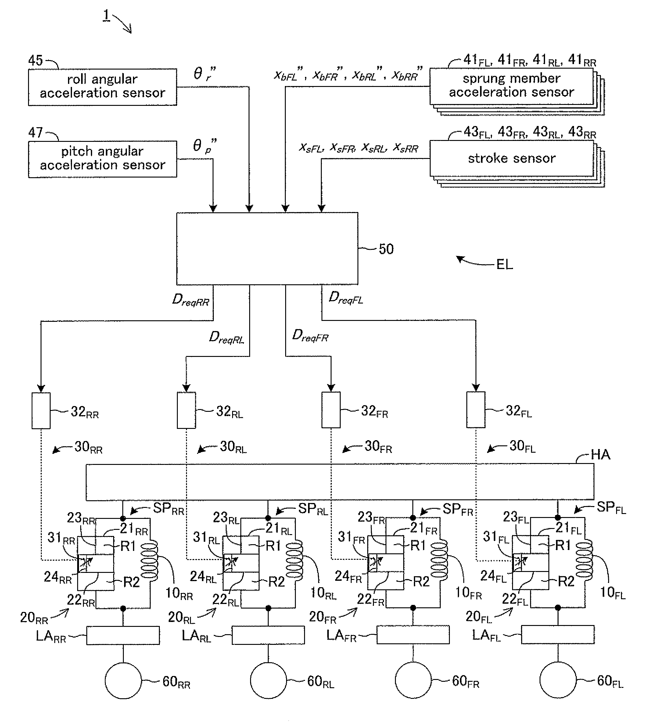
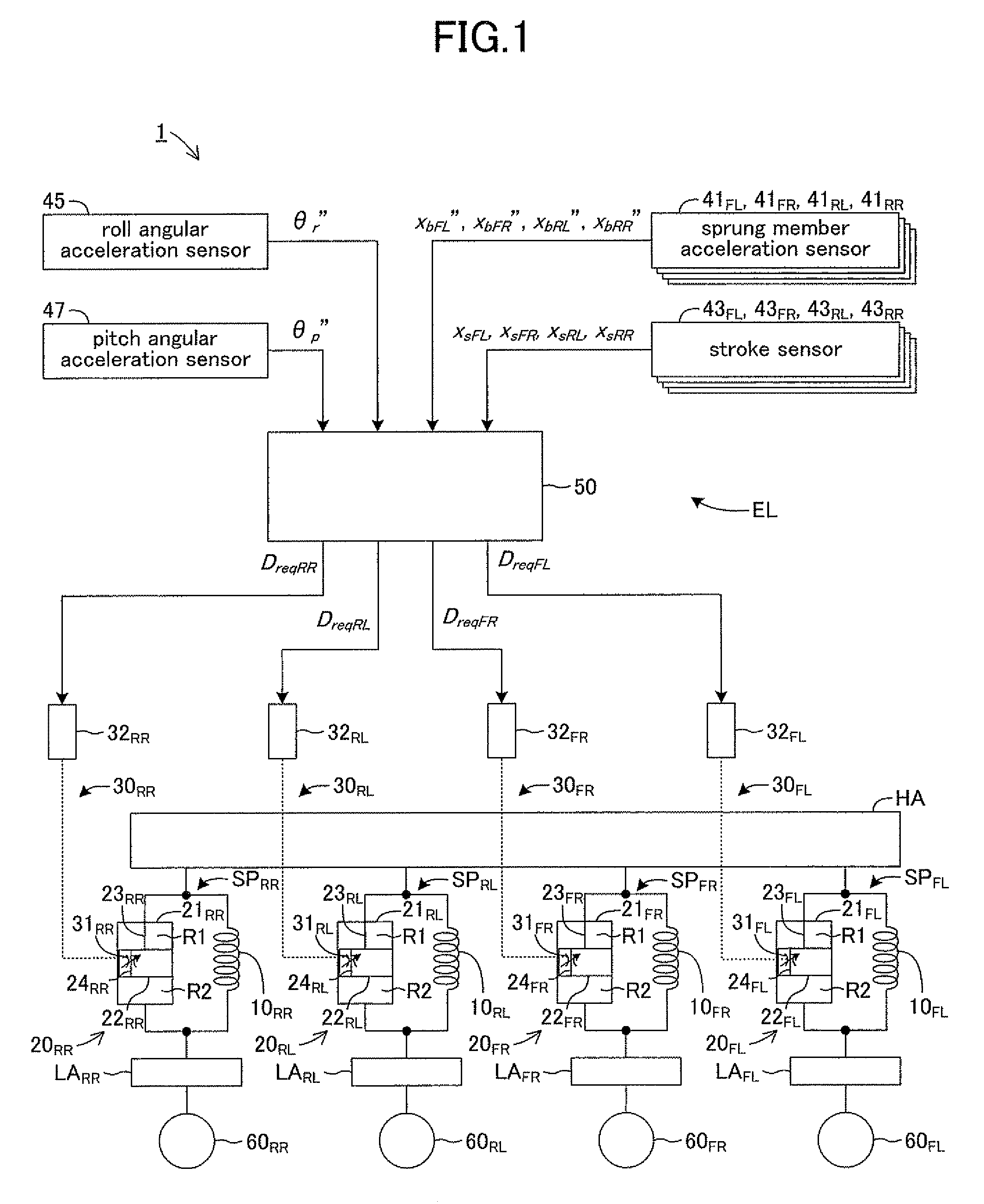
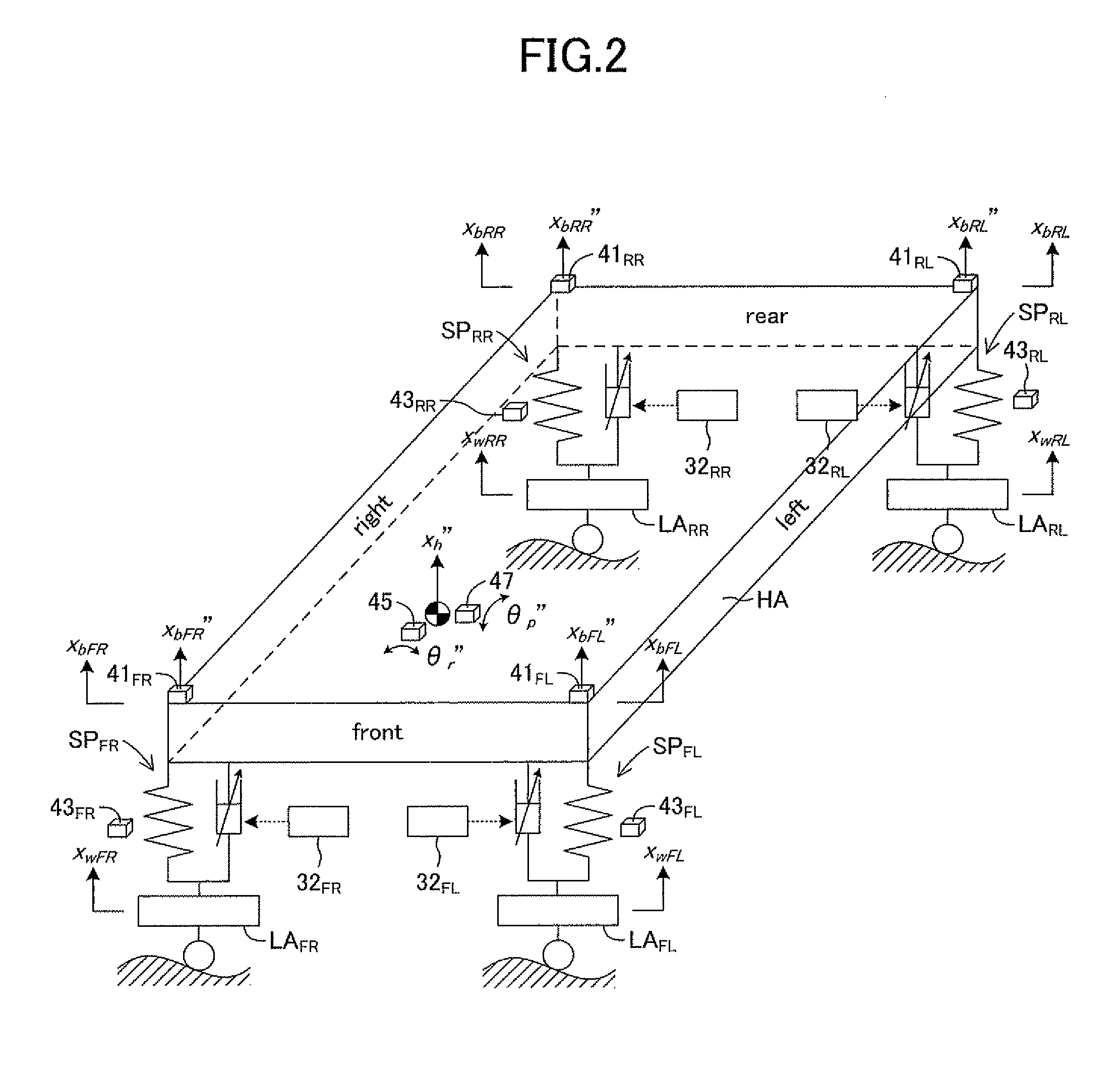
[0042]FIG. 1 shows an entire schematic diagram of a suspension control apparatus according to the present embodiment. As shown in FIG. 1, the suspension control apparatus 1 comprises four suspension apparatuses (suspension mechanisms) SPFL, SPFR, SPRL, SPRR and an electric control device EL. Each of the suspension apparatuses SPFL, SPFR, SPRL, SPRR supports a sprung member HA including a vehicle body and the like. Each of the four suspension apparatuses SPFL, SPFR, SPRL, SPRR has a structure identical to each other. The structure of the suspension apparatus SPFL is therefore described as a representative of these apparatuses.

[0043]The suspension apparatus SPFL comprises a spring 10FL and a damper 20FL. The spring 10FL and the damper 20FL are interposed / disposed in parallel with each other between the sprung member HA and an unsprung member LAFL. The suspension apparatus SPFL is, at its upper end side, connected with...


PUM


Abstract

A control mode for a damping force characteristic is set to be a variable control when a product of the sum xb′ of sprung member speeds and a sprung-member-unsprung-member-relative-speed xs′ is positive. Accordingly, when the vibration in a middle / high frequency range is not being input to a suspension apparatus, an operation of a variable throttle mechanism is controlled so that a step number representing the damping force characteristic of a damper varies with a vibration state of a sprung member HA based on a Nonlinear H∞ control theory. When the product of xb′ and xs′ is negative, the control mode is set to be an operation prohibiting control. When the vibration in the middle / high frequency range is input to the suspension apparatus, operation of the variable throttle mechanism is prohibited, and suppresses an increase in the operation frequency or in the operation amount of the variable throttle mechanism.

Description

TECHNICAL FIELD[0001]The present invention relates to a damping force control apparatus for controlling a damping force characteristic of a damper used for a vehicle suspension apparatus and the like.BACKGROUND ART[0002]A vehicle suspension apparatus supporting a sprung member such as a vehicle body comprises a spring and a damper, which are interposed / disposed between the sprung member and an unsprung member. A damping force control apparatus for variably controlling a damping force characteristic of the damper is known. Such a damping force control apparatus variably controls the damping force characteristic of the damper in response to a vibration state / condition of the sprung member on the basis of, for example, a skyhook control theory or a Nonlinear H .INF. (H∞) control theory.[0003]Japanese Patent Application Laid-Open (kokai) No. Hei 6-247117 discloses a suspension apparatus comprising a damper having a structure configured in such a manner that, when either one of “a dampin...

Claims


Application Information

Patent Timeline
Patent Type & Authority Patents(United States)
IPC IPC(8): B60G17/06
CPCB60G17/018B60G17/08F16F15/002B60G2500/10B60G2600/1875B60G2400/202
Inventor HAYASHI, TAISUKEMIZUTA, YUICHILIU, YANQING
Owner TOYOTA JIDOSHA KK
Learn More