
Devices for mobility assistance and infusion management

a technology for infusion management and mobility assistance, applied in the direction of roller massage, machine support, transportation and packaging, etc., can solve the problems of special safety problems and inadequate safety concerns, and achieve the effects of facilitating safe and reliable ambulation, enhancing patient care, and promoting safe patient ambulation

Active Publication Date: 2019-05-28
FIREFLY MEDICAL
View PDF113 Cites 7 Cited by
  • Summary
  • Abstract
  • Description
  • Claims
  • Application Information

AI Technical Summary

Benefits of technology

Enhances patient and caregiver safety by providing stable and reliable ambulation, reduces the risk of falls, and allows for efficient storage and deployment, minimizing the need for multiple caregivers.

Problems solved by technology

A walking patient, however, presents special safety problems in terms of ensuring the supporting pole is stable and does not tip or hinder the patient or caregiver when it is moving with the patient.
This safety concern is not adequately addressed by current IV poles that have a vertical pole connected to a wheeled base.

Method used


Image

  • Devices for mobility assistance and infusion management
  • Devices for mobility assistance and infusion management
  • Devices for mobility assistance and infusion management

Examples


example 1

Mobility Assistance Device with Extendible Pole

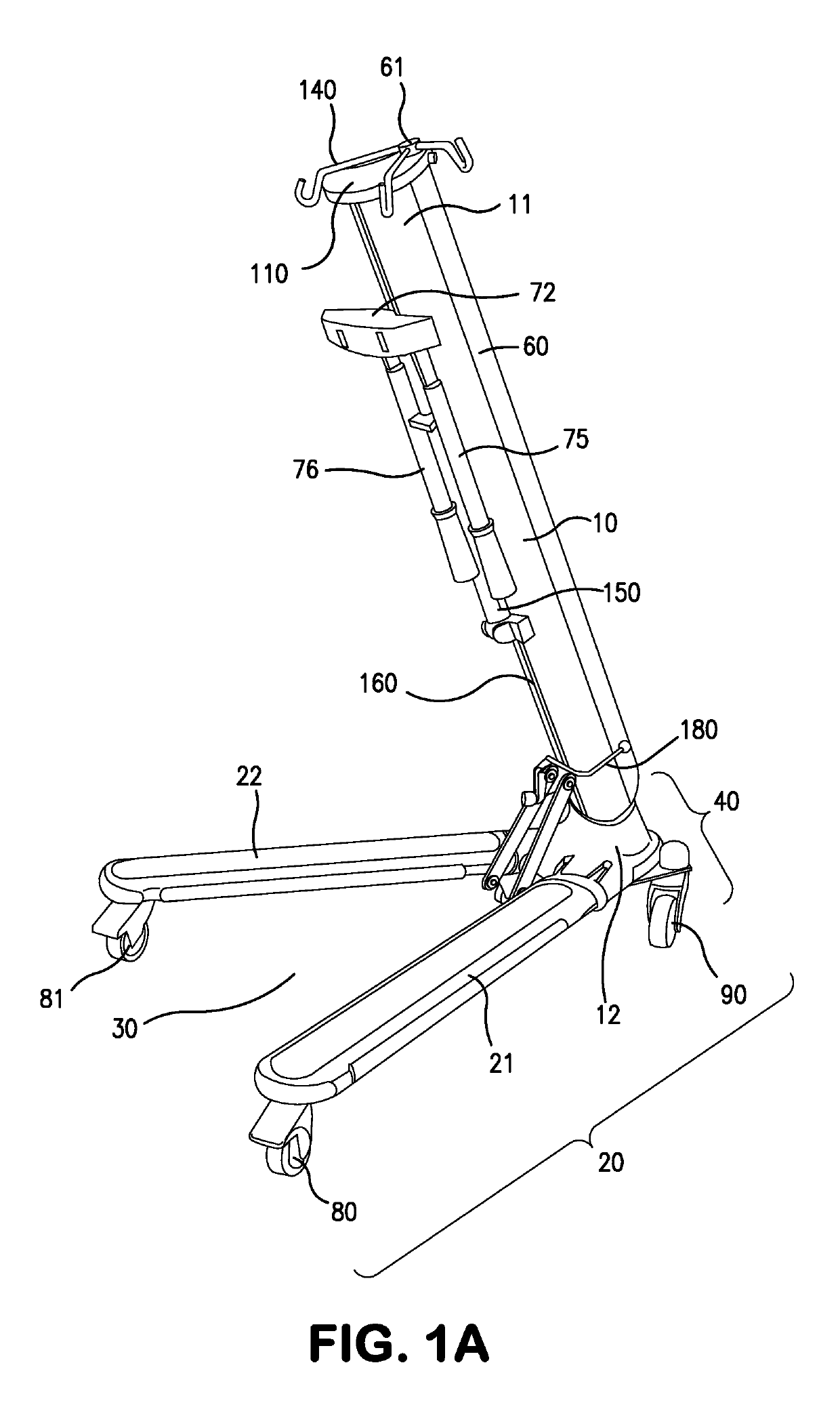
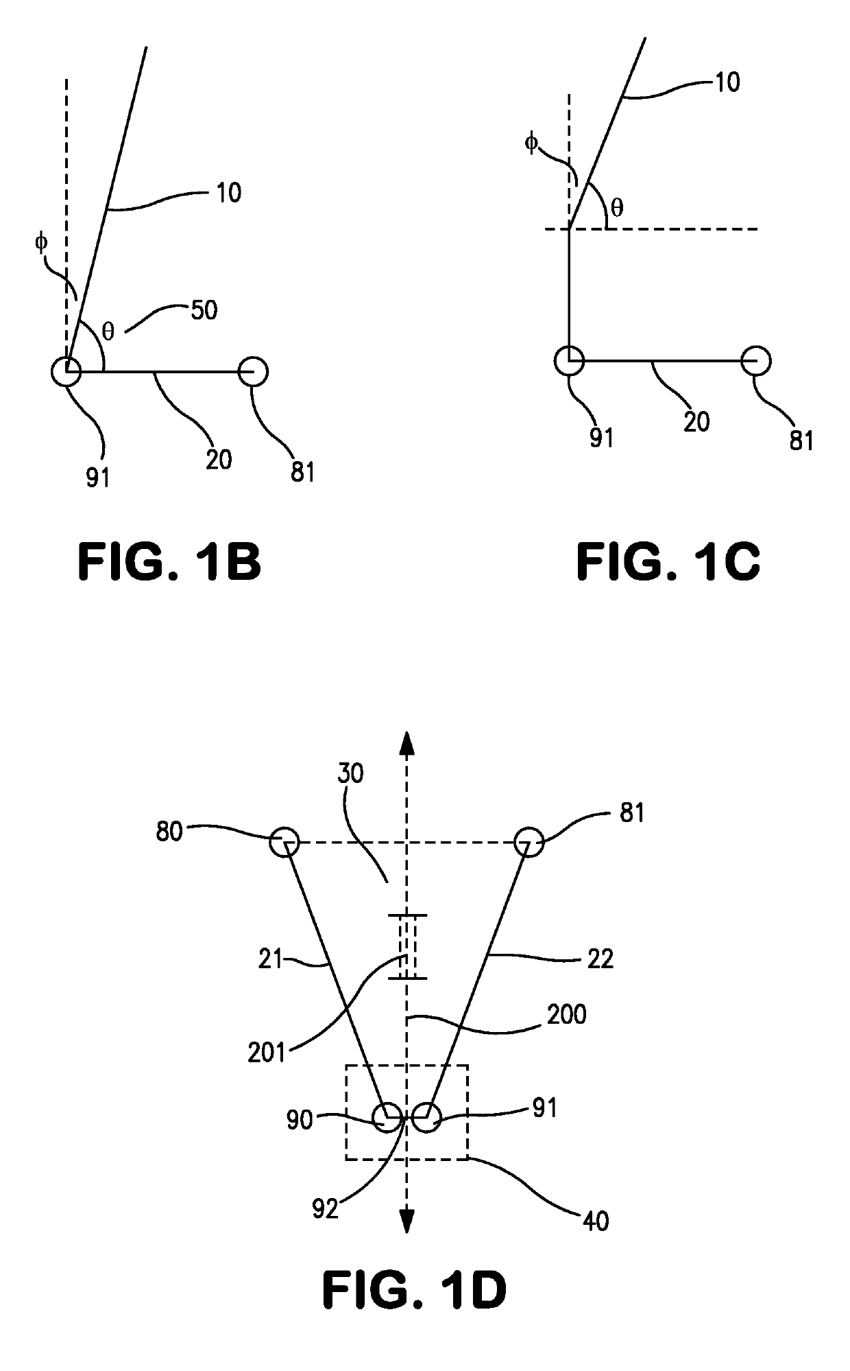
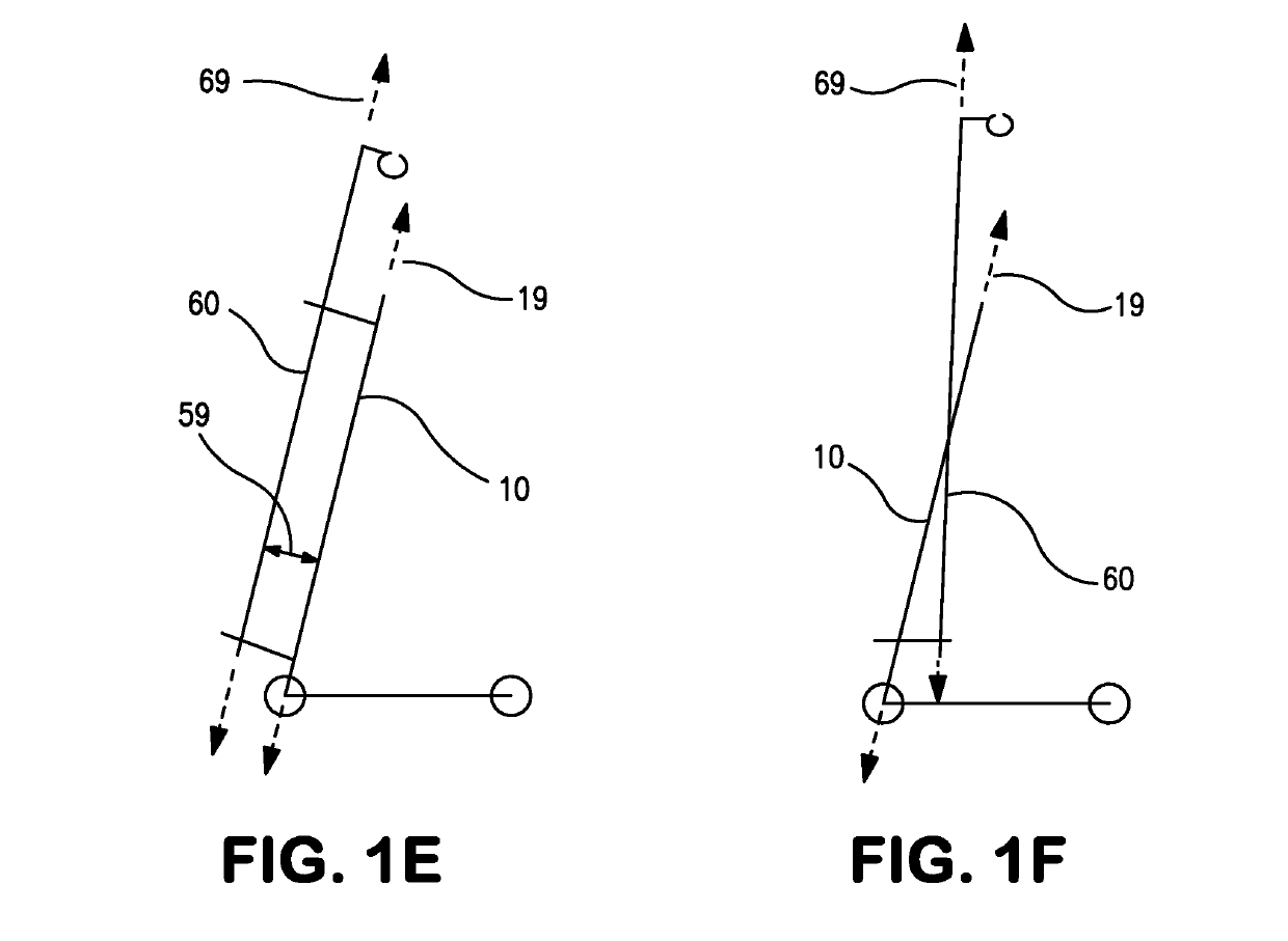
[0104]The mobility assistance device (“device”) in its most basic configuration comprises a mast 10 connected to a base 20 and having a pole 60 positioned along the mast 10 surface. (FIG. 1A). The pole may be extendible. FIGS. 1-5 show a device in a base deployed configuration. The base 20 has a base first leg 21 and second leg 22 connected to the mast bottom end 12. The mast 10 forms a mast angle 50, a non-zero angle (Φ) relative to vertical and an acute angle (θ) relative to the base 20, as schematically illustrated in FIG. 1B.

[0105]First wheel 80 and second wheel 81 are attached to base legs 21 and 22, and third wheel 90 and fourth wheel 91 are attached to the mast bottom end 12 at a vertex region 40 to form a two-sided base footprint 30 (FIGS. 1A, 10 and 2). The two sides of the base footprint 30 correspond to the base legs 21 and 22. FIG. 10. The device can have one wheel attached to the mast bottom end 12. The exemplified embodime...

example 2

Height-Adjustable Mobility Handle

[0113]A useful embodiment of the invention is a system that has a mobility handle 70 that comprises a platform 72, and a first and second grip handle 75 and 76 (FIGS. 2-6). In this aspect, the mobility handle is height adjustable, but along a handle plane that is substantially parallel or parallel to the base footprint. In this aspect, the mobility handle 70 that is height adjustable can be by a number of mechanisms. In the exemplified embodiment, the mobility handle first platform end 73 engages with a groove 160 in the inward-facing surface 14 of the mast 10, for height adjustability along the mast (FIGS. 6 and 8). The first and second grip handles 75 and 76 engage the second platform end 74, where they may pivot or rotate downward into a stored position by engagement mechanism 78 and may be height-adjustable by quick release cam 77 mechanism (FIGS. 1 and 8). Alternatively, the grip handles can be moved into a storage position telescopingly or by o...

example 3

Mounting Arm

[0114]The embodiment illustrates a rotable mounting arm 150 connected to the mast inward-facing surface 14 for holding additional medical devices and other relatively heavy objects (e.g. small platforms, power supplies, pleur-evac etc.). FIGS. 2-5 show the mounting arm 150 in its deployed position. The mobility assistance device can be used with the mounting arm in its stored configuration (FIG. 1A).


PUM


Abstract

Provided are mobility assistance devices, particularly useful in medical settings where a patient ambulation is desired but the patient remains connected to one or many medical components. The system comprises a mast connected to a base, wherein the mast is angled with respect to the base and from which any number of medical components is supported. The device geometry and connections ensure the device is extremely stable and tip-resistant. Also provided are oxygen tank holders to reliably and conveniently hold oxygen tanks and power management systems that reliably provide electrical power without impacting device performance or mobility. The device is deployable to permit conversion between a compact storage configuration and a stable deployed configuration.

Description

CROSS-REFERENCE TO RELATED APPLICATIONS[0001]This application claims the benefit of and priority to U.S. Provisional Patent App. Nos. 61 / 947,809 filed Mar. 4, 2014 (91-13P1), 61 / 880,644 filed Sep. 20, 2013 (91-13P) and 61 / 856,431 filed Jul. 19, 2013 (173-06P1), each of which is hereby incorporate by reference to the extent not inconsistent herewith.BACKGROUND OF THE INVENTION[0002]The invention is generally in the field of a mobile support stand that is capable of folding into a compact storage configuration, and has specific applications in the medical field, including providing mobility assistance to a person connected to an infusion pump and attendant medical components. Accordingly, the device is useful as a mobility assistance device to a person in a medical setting. As discussed in U.S. Pat. Nos. 8,136,773 and 8,534,616, it is important for patient rehabilitation and recovery that a patient be able to walk, even when connected to a medical component, after a medical procedure....

Claims


Application Information

Patent Timeline
Patent Type & Authority Patents(United States)
IPC IPC(8): A61G12/00A61M5/14B62B3/02A61B50/13A61G7/05A61H3/04B62B5/00F16M11/28F16M11/38F16M11/42A61H3/00A61G7/10
CPCA61B50/13A61G7/0503A61H3/04A61M5/1415A61M5/1418B62B3/02F16M11/28F16M11/38F16M11/42B62B5/002A61H2201/0192A61G7/1046A61H2003/002A61H15/00
Inventor SCHOENIG, DARRELLSCHMUTZER, STEPHEN E.
Owner FIREFLY MEDICAL
Learn More