Electrical receptacle connector including a baffle plate

a technology of electrical receptacles and baffle plates, which is applied in the direction of coupling devices, two-part coupling devices, electrical apparatus, etc., can solve the problems of affecting the operation or signal transmission of devices whose devices are affecting the operation of electronic devices connected to the connector, and generating noise of 3.0 electrical receptacle connectors during data transmission, so as to reduce noise, reduce noise, and reduce noise.

Active Publication Date: 2019-05-28
ADVANCED CONNECTEK INC
View PDF3 Cites 5 Cited by
  • Summary
  • Abstract
  • Description
  • Claims
  • Application Information

AI Technical Summary

Benefits of technology

[0017]As above, the baffle plate is at the rear portion of the metallic shell, and the conductive ground legs are at two sides of the metallic shell. Therefore, when the electrical receptacle connector transmits data, the noise produced by the data is shielded by the baffle plate, and the noise current formed by the noise is guided to the circuit board through the conductive ground legs which are in contact with the circuit board, thus the noise is grounded and diminished. The conductive ground legs are adjacent to the baffle plate. That is, the conductive ground legs are at the two sides of the rear portion of the metallic shell and in contact with the sidewalls of the baffle plate. Hence, the current flowing through the baffle plate is guided to the circuit board through the conductive ground legs, which has a shorter current path. Therefore, the noise current would not have an antenna effect easily on the transmission path. Accordingly, the noise spreading can be reduced, and the problems of the electromagnetic interference (EMI) and the radiofrequency interference (RFI) can be improved.

Problems solved by technology

However, the more electromagnetic waves the devices generate, the worse radiofrequency interference (RFI) affects the operation or the signal transmission between devices.
Existing USB 3.0 electrical receptacle connectors produce noise during data transmission.
As a result, the current (i.e., the noise current) has to be transmitted with over a longer distance for grounding, and the noise current would have an antenna effect on the transmission path thus spreading the noise and affecting the operation of an electronic device connected to the connector.

Method used


Image

  • Electrical receptacle connector including a baffle plate
  • Electrical receptacle connector including a baffle plate
  • Electrical receptacle connector including a baffle plate

Examples


first embodiment

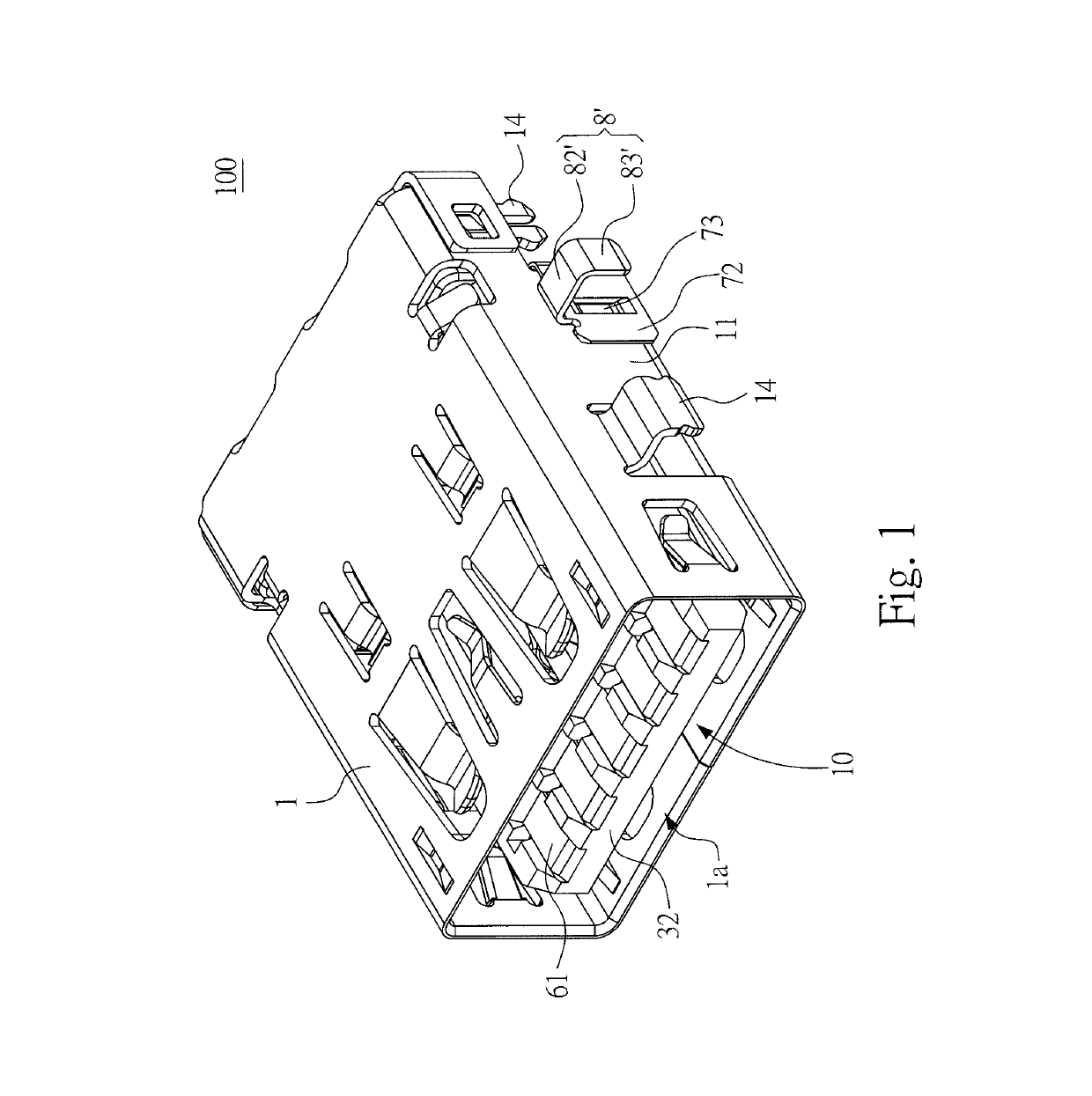
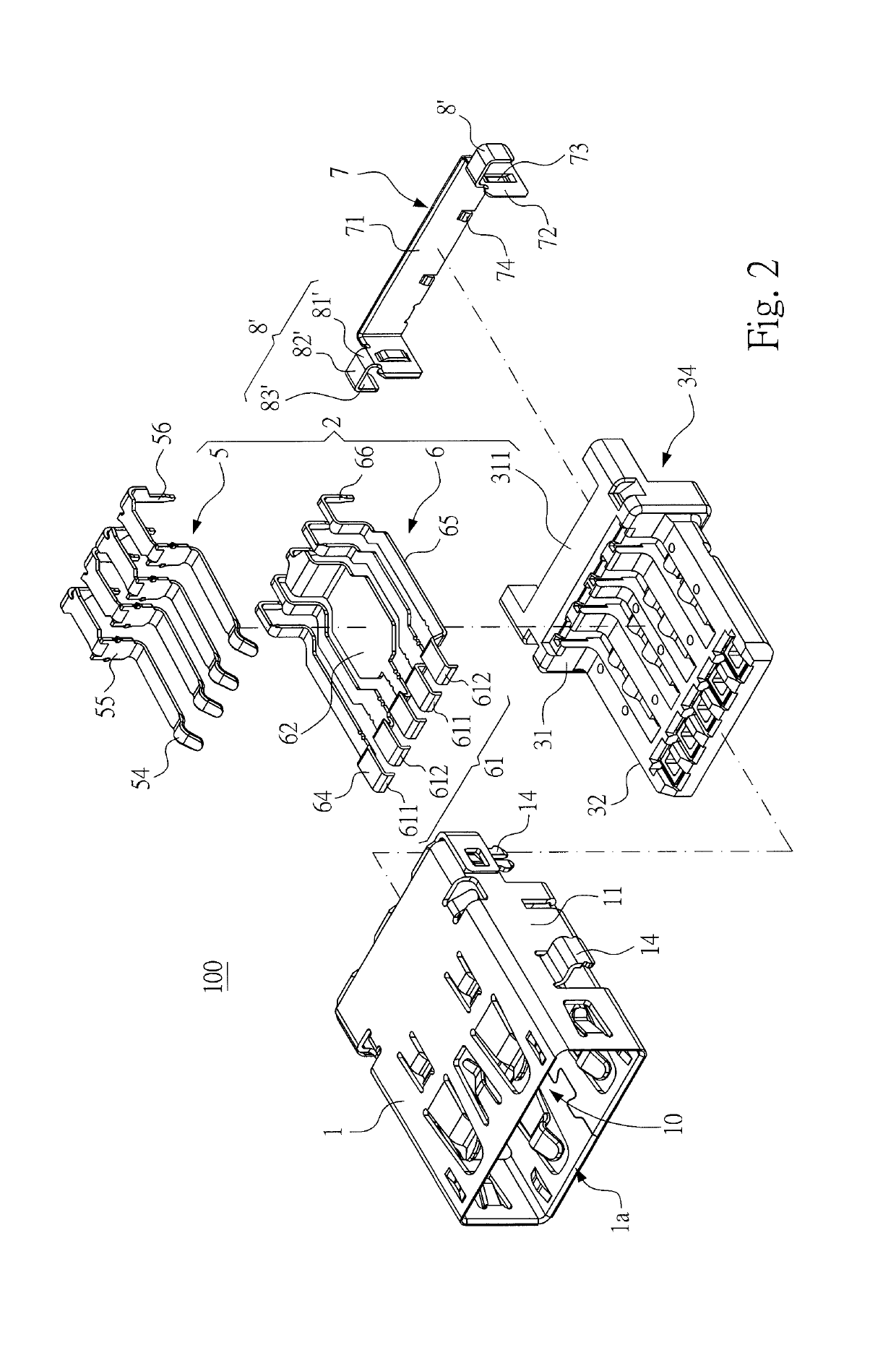
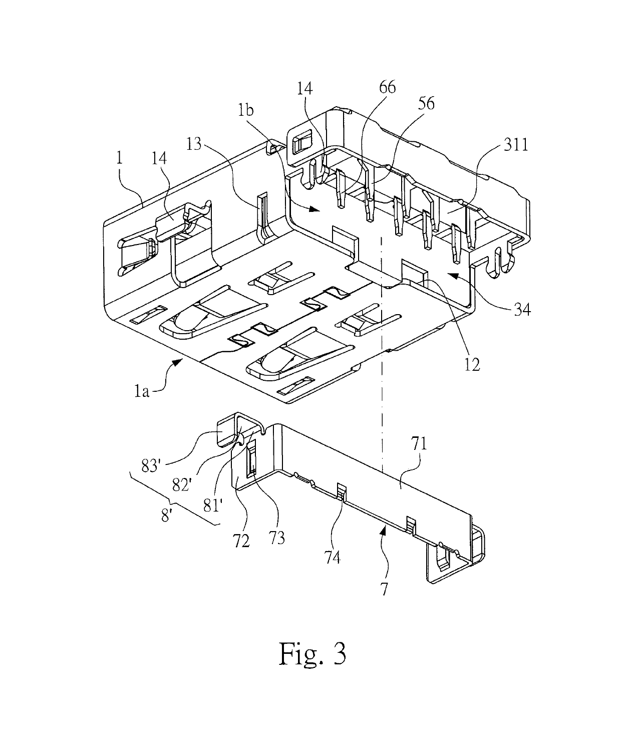
[0035]Please refer to FIGS. 2 to 4. FIG. 4 illustrates a schematic perspective view showing the metallic shell of the connector is assembled with the baffle plate, according to the In this embodiment, the baffle plate 7 is at the rear end 1b. The baffle plate 7 comprises a main body 71 and two sidewalls 72. The main body 71 is flush with a rear lateral surface of the base portion 31 and in contact with a rear periphery 12 of the metallic shell 1. The two sidewalls 72 respectively extend from two sides of the main body 71 toward two outer surfaces 11 of two sides of the metallic shell 1. In this embodiment, the main body 71 is an elongated plate, and the main body 71 and the two sidewalls 72 are reverse U shaped in a top view. When the first terminals 5 and the second terminals 6 transmit data, the main body 71 receives the noise produced by the data, and the main body 71 also shields the noise to reduce the spreading of the noise toward the rear portion of the metallic shell 1.

[003...

second embodiment

[0046]Please refer to FIGS. 7 and 8. In the second embodiment, the conductive ground legs 8″ extend outwardly from the two sides of the rear portion of the metallic shell 1, and a recessed hole 15 is at a bottom portion of each of the conductive ground legs 8″. In other words, as shown in FIGS. 7 and 8, two recessed holes 15 are formed on the two sides of the rear portion of the metallic shell 1. When the baffle plate 7 is assembled to the rear portion of the metallic shell 1, the two sidewalls 72 are at bottom portions of the conductive ground legs 8″ to shield the two recessed holes 15, respectively.

[0047]Please refer to FIGS. 7 and 8. In the second embodiment, the conductive ground legs 8″ further comprise an insertion leg 83″. Each of the insertion legs 83″ extends outwardly from an edge of the corresponding extension portion 82″. The insertion legs 83″ extend vertically and downwardly to form vertical legs (legs manufactured by through-hole technologies) and are in contact with...


PUM


Abstract

An electrical receptacle connector includes a metallic shell, a terminal module in the metallic shell, a baffle plate at a rear portion of the metallic shell, and conductive ground legs. Accordingly, the baffle plate is at the rear portion of the metallic shell, and the conductive ground legs are at two sides of the metallic shell. Therefore, during the connector transmits data, the produced noises are shielded by the baffle plate, and the current formed by the noises is guided to a circuit board through the conductive ground legs, thus the noises are grounded and diminished. The conductive ground legs are adjacent to the baffle plate. Hence, the current flowing through the baffle plate is guided to the circuit board through the conductive ground legs, with a shorter path. Therefore, the current would not have antenna effect easily on the path, and the noise spreading can be reduced.

Description

CROSS-REFERENCE TO RELATED APPLICATION[0001]This non-provisional application claims priority under 35 U.S.C. § 119(a) to Patent Application 106200365 in Taiwan, R.O.C. on Jan. 9, 2017, the entire contents of which are hereby incorporated by reference.FIELD OF THE INVENTION[0002]The instant disclosure relates to an electrical connector, and more particular to an electrical receptacle connector.BACKGROUND[0003]Nowadays, electronic devices generate more electromagnetic waves as they are becoming more multifunctional. However, the more electromagnetic waves the devices generate, the worse radiofrequency interference (RFI) affects the operation or the signal transmission between devices.[0004]Existing USB 3.0 electrical receptacle connectors produce noise during data transmission. A conventional USB 3.0 electrical receptacle connector is assembled to a crack at one side of a circuit board by a sinking technique. In addition, a shielding iron sheet is assembled at a rear portion of a meta...

Claims


Application Information

Patent Timeline
Patent Type & Authority Patents(United States)
IPC IPC(8): H01R24/60H01R13/6596H05K5/04H01R13/6471H01R13/6585H01R24/64H01R13/6587H01R13/6466H01R13/6594H01R12/72H01R13/516H01R107/00
CPCH01R13/6596H01R13/6471H01R13/6585H01R24/60H05K5/04H01R12/722H01R2107/00H01R13/516H01R13/6466H01R13/6587H01R13/6594H01R24/64H01R12/724H01R13/405H01R13/502H01R13/652H01R13/6581H01R13/6595
Inventor WANG, YAO-TEHONG, RUEI-SI
Owner ADVANCED CONNECTEK INC
Why Eureka
Try Eureka