
Track based lighting and installation method

a technology of track and installation method, which is applied in the direction of lighting and heating apparatus, coupling device connection, lighting support device, etc., can solve the problems of high demands on coupling parts, large work and cost, and segments with a maximum length of 4.5 meters, and achieves easy installation, simple installation task, and resistance to bending or rolling

Inactive Publication Date: 2019-05-28
SIGNIFY HLDG BV
View PDF14 Cites 0 Cited by
  • Summary
  • Abstract
  • Description
  • Claims
  • Application Information

AI Technical Summary

Benefits of technology

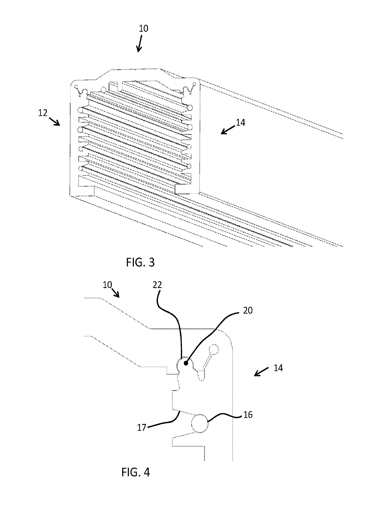
[0010]This means the length of the structure (when unrolled) may be longer than would be able to be transported in a straight configuration. This reduces (or eliminates) the need for connectors between multiple sections. This therefore reduces the time and cost of installing the lighting track. The installation has a low number of operations, a low number of components, with low space and weight and therefore low transportation costs. The length can easily be adjusted (by cutting) either on site or before transportation. By the transformation of the structure from its open state into the assembled state, the flat, essentially 2 dimensional form factor of the structure in its open state, which enables the structure to be rollable then, changes into a voluminous, essentially 3 dimensional channel which renders the structure to be rigid and in a non-rollable state. The channel then can be considered to form the trunk or housing of the lighting track / system. Rigid in this context means that the structure is essentially incapable of or relatively highly resistant to bending and / or deformation, and preferably is self-supporting over distances of, for example at least 0.75 meter, 2.5 meter or 4 meter. The rigidity of the structure renders the structure capable of being suspended in free space and / or act as such, hence without the need for a separate or additional housing or carrier, as a support / mounting structure for lighting units, for example spot light lamps, mounting or removal of said lighting units can easily be done via the front side of the channel.
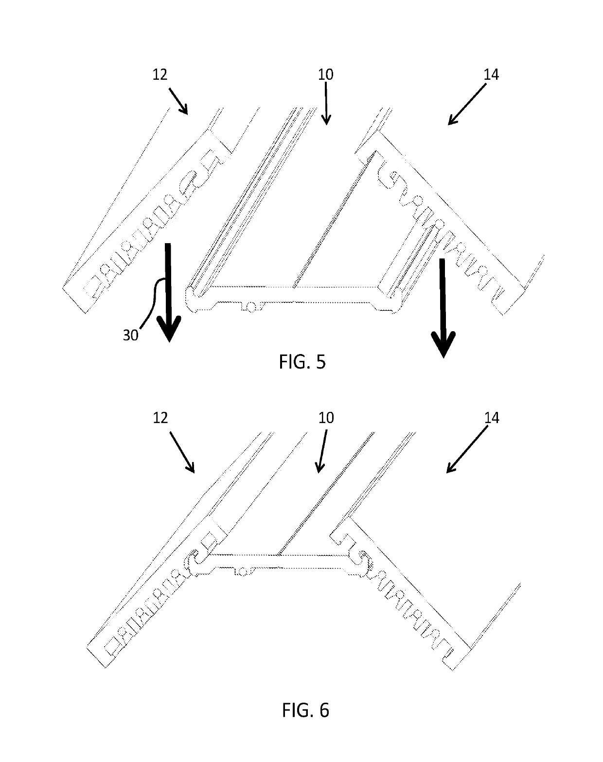
[0012]In the open state, the three sections may be rolled as a single entity. This keeps the installation task as simple as possible. It also means the base section and the opposing side sections may be formed as a single component.
[0013]Each opposing side section may comprise a first lock feature which engages with a corresponding second lock feature of the base section to lock the structure in the closed state. The structure is thus simply folded from a flat profile to the channel profile, and it locks itself in place. In the channel profile, the structure gains rigidity and thus resists bending or rolling. This means it is easy to install in long lengths. It may be supported at periodic intervals, for example each 1 meter, 2 meter or 5 meter, to maintain a desired straight path when installed.
[0014]In a second set of examples, each side section and the base section are separate elements, adapted to be rolled separately, and coupled together in an unrolled state. This reduces the size of the parts when being transported, although additional assembly is required on site.

Problems solved by technology

Typically, the segments have a maximum length of 4.5 meters, mainly limited by the transportation requirements, since the segments need to fit in a truck or minivan, and also possibly in elevators in buildings.
This causes a lot of work and cost, and the demands on the coupling pieces are high to create and maintain a straight line.

Method used


Image

  • Track based lighting and installation method
  • Track based lighting and installation method
  • Track based lighting and installation method

Examples


Embodiment Construction

[0041]The invention provides a lighting track support structure which comprises a base section and opposing side sections. These sections are rollable for transportation in a roll. This means the length of the structure (when unrolled) may be longer than would be able to be transported in a straight configuration. This reduces (or eliminates) the need for connectors between multiple sections. This therefore reduces the time and cost of installing the lighting track.

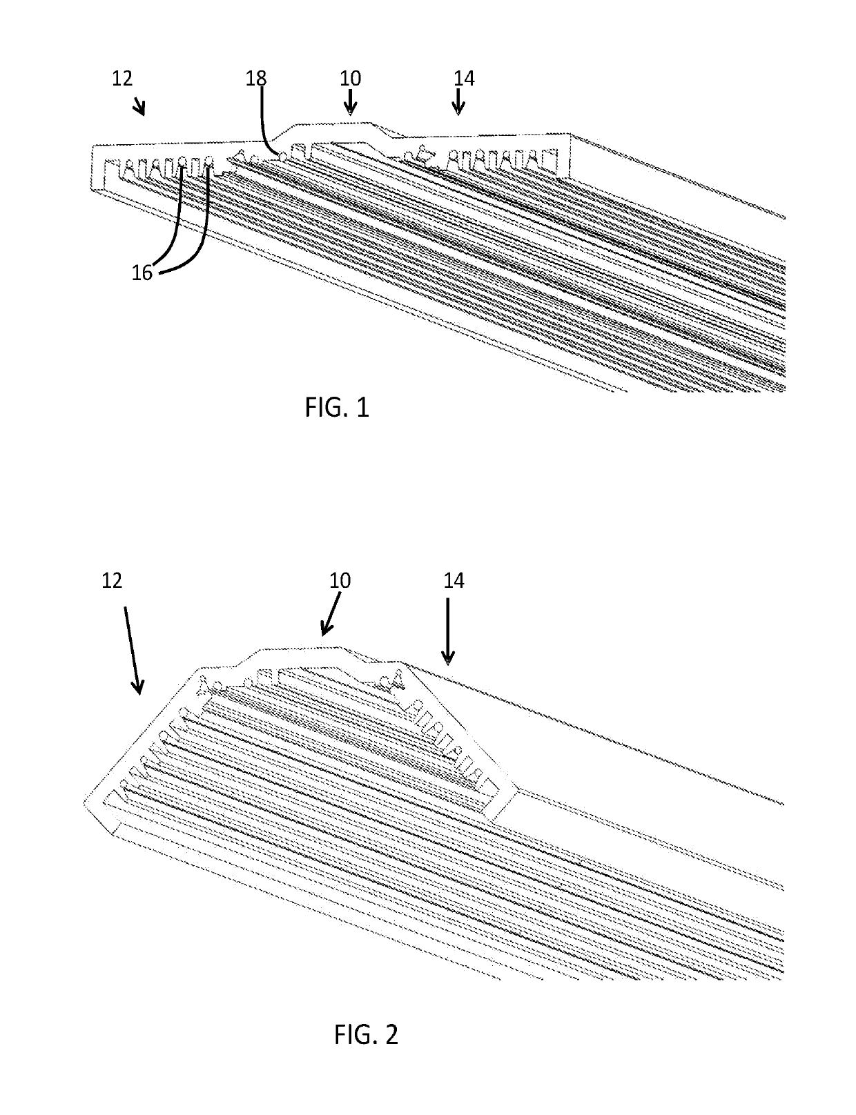
[0042]FIG. 1 shows a first example of lighting track support structure, which comprises a support frame and electrical conductors carried by the support frame.

[0043]The structure comprises a base section 10 and opposing side sections 12, 14. FIG. 1 shows the side sections oriented in an open shape so that the complete structure forms a substantially flat web. The overall shape is generally planar, although there are surface features for example for retaining electrical conductors 16 in the side wall, and optionally also o...


PUM


Abstract

A lighting track support structure comprises a base section and opposing side sections. These sections are rollable for transportation in a roll. This means the length of the structure (when unrolled) may be longer than would be able to be transported in a straight configuration. This reduces (or eliminates) the need for connectors between multiple sections. This therefore reduces the time and cost of installing the lighting track.

Description

CROSS-REFERENCE TO PRIOR APPLICATIONS[0001]This application is the U.S. National Phase application under 35 U.S.C. § 371 of International Application No. PCT / EP2016 / 055436, filed on Mar. 14, 2016 which claims the benefit of European Patent Application No. 15161045.8, filed on Mar. 26, 2015. These applications are hereby incorporated by reference herein.FIELD OF THE INVENTION[0002]The invention relates to track based lighting systems.BACKGROUND OF THE INVENTION[0003]In both retail and industrial lighting applications, track based systems are often used create linear lighting systems. The track is defined by trunking, which creates a mechanical and electrical infrastructure to which lighting fixtures can be mounted at desired locations.[0004]This provides a flexible lighting system, which can be configured according to the lighting requirements at different areas within the retail or industrial space.[0005]The lines may have a significant length, of many meters, or even tens of meters...

Claims


Application Information

Patent Timeline
Patent Type & Authority Patents(United States)
IPC IPC(8): F21V17/00H01R25/14F21V21/002F21V21/35
CPCH01R25/145H01R25/14F21V21/35F21V21/002
Inventor DE GIER, RONALD CORNELISMORO, RAFALORLOWSKI, KAROL
Owner SIGNIFY HLDG BV
Learn More