Heat treating assembly and method

a technology of heat treatment and assembly, applied in the direction of metal-working equipment, welding equipment, manufacturing tools, etc., can solve the problems of reducing precisely altering the defined area, and limiting the alteration of the substrate, so as to overcome the inadequacies, reduce the likelihood of substrate failure, and limit the effect of substrate alteration

Active Publication Date: 2006-03-09
FEDERAL MOGUL WORLD WIDE LLC
View PDF33 Cites 3 Cited by
  • Summary
  • Abstract
  • Description
  • Claims
  • Application Information

AI Technical Summary

Benefits of technology

[0010] Accordingly, the subject invention provides an assembly and a method that overcomes the inadequacies that characterize the related art. Specifically, the subject invention utilizes the tool to limit the altering of the substrate by conducting heat energy away from the substrate. Therefore, the heat energy precisely alters the defined area without altering additional areas of the substrate unintentionally. With reference to the related art examples described above, the subject invention ensures little or no unintentional altering of the vertical surface occurs. Only the desired area is hardened which decreases the likelihood that the substrate may fail. The tool also reduces the time and cost required to alter the desired area. The laser does not have to be precisely controlled while being scanned and the area can be treated with a single pass of a line of light-type laser. The subject invention further provides that the tool minimizes distortion of the substrate as a result of being treated.

Problems solved by technology

Therefore, the heat energy precisely alters the defined area without altering additional areas of the substrate unintentionally.
Only the desired area is hardened which decreases the likelihood that the substrate may fail.

Method used


Image

  • Heat treating assembly and method
  • Heat treating assembly and method
  • Heat treating assembly and method

Examples


Embodiment Construction

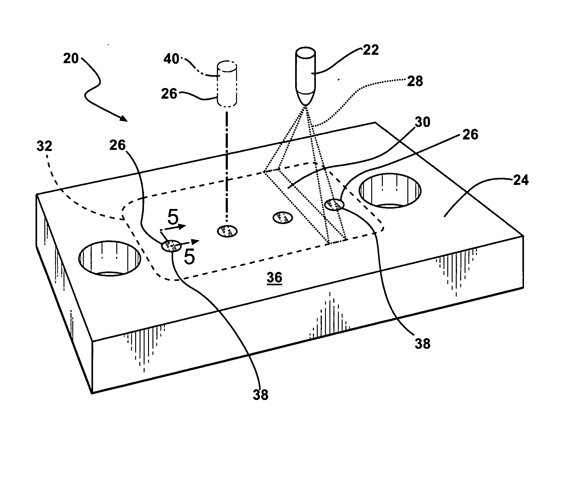
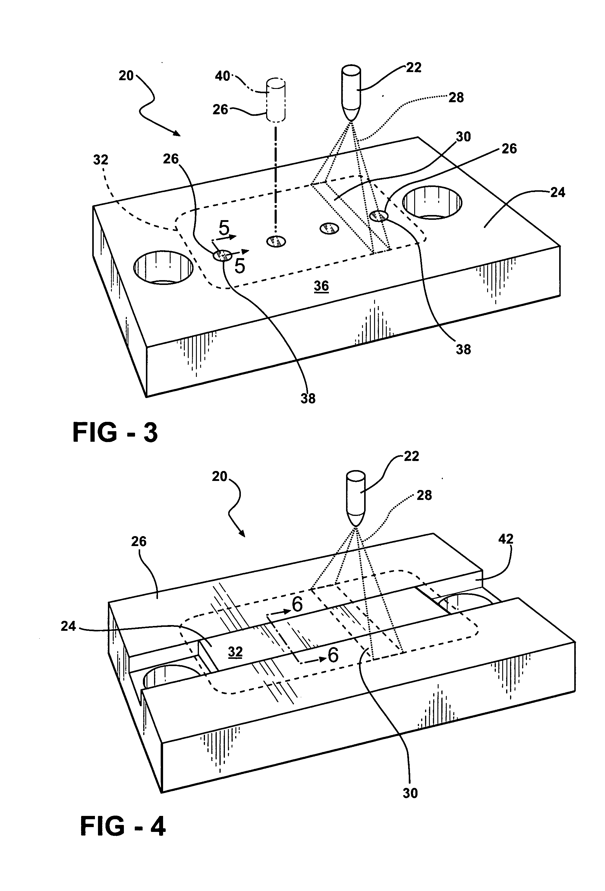
[0018] A heat treating assembly is illustrated generally at 20 in FIG. 3. The heat treating assembly 20 comprises a laser 22, a substrate 24, and a tool 26. The laser 22 emits laser energy 28 directed toward the substrate 24 and the tool 26. The substrate 24 absorbs the laser energy 28 and heat energy alters the substrate 24. The substrate may be altered in various ways, such as, but not limited to, etching, marking, annealing, precipitation hardening, and the like.

[0019] Various lasers 22 emit laser energy 28 having various wavelengths depending upon the type of laser. The laser 22 may be a solid state laser, a gas laser, an excimer laser, a dye laser, or a semiconductor laser. Illustrative examples of solid state lasers include, but are not limited to, ruby-type lasers and neodymium:yttrium-aluminum garnet-type (Nd:YAG) lasers. The Nd:YAG lasers typically produce the laser energy 28 having a wavelength of about 1,064 nanometers. Illustrative examples of the gas lasers include, bu...


PUM

PropertyMeasurementUnit
thermal conductivityaaaaaaaaaa
reflectivityaaaaaaaaaa
wavelengthaaaaaaaaaa

Abstract

The subject invention provides a heat treating assembly. The heat treating assembly comprises a laser, a substrate, and a tool. The laser emits laser energy directed toward the substrate and the tool. The substrate absorbs the laser energy and produces heat energy within the substrate that alters the substrate. The tool is disposed in removable contact with the substrate to conduct the heat energy away from the substrate to limit the altering of the substrate. Preferably, the tool has a thermal conductivity greater than that of the substrate and is more preferably a copper material, a gold material, a silver material, or an aluminum material.

Description

BACKGROUND OF THE INVENTION [0001] 1. Technical Field [0002] The subject invention relates to a heat treating assembly and a method for altering a defined area of a substrate with laser energy. [0003] 2. Related Art [0004] Various heat treating assemblies are known to those skilled in the art that employ lasers and that use laser energy to treat a substrate. One drawback of treating the substrate with the laser is that once the laser emits the laser energy as a beam, it is difficult to restrict the energy to an area of treatment. The laser energy once absorbed by the substrate has a tendency to be conducted by the material of the substrate to regions beyond the areas directly exposed to the laser energy. This conduction makes it difficult it to precisely control the area of treatment. Known laser treatment systems also employ a relatively narrow beam of light in relation to the area to be treated in an effort to control the application of the laser energy to the desired area. Such a...

Claims


Application Information

Patent Timeline
Patent Type & Authority Applications(United States)
IPC IPC(8): B23K26/08
CPCB23K26/422B23K26/702B23K26/352B23K26/60
Inventor LINETON, WARRAN BOYDBAGNALL, CHRISTOPHER
Owner FEDERAL MOGUL WORLD WIDE LLC
Why Eureka
Try Eureka