Motorized cutting tool with guard

a guard and motorized cutting technology, applied in the field of portable motorized cutting tools, can solve the problems of/or the transmission connection of the motor, affecting the cutting member, and affecting the use of the hand of the user

Inactive Publication Date: 2019-06-04
PELLENC SA
View PDF10 Cites 1 Cited by
  • Summary
  • Abstract
  • Description
  • Claims
  • Application Information

AI Technical Summary

Benefits of technology

[0012]The present invention aims to overcome these difficulties mentioned above. It also aims to provide both good safety for use of the tool and quick and easy access to the members subject to maintenance operations.
[0017]That way, in the open position of the cover, it is possible to go ahead with maintenance operations such as cleaning the members thereof, and in particular the transmission, replacing the cutting member, greasing and possibly maintenance operations requiring access to the electronic card via the connector.
[0019]Because of these arrangements, the removable cover can be taken off quickly and without tools. Because of the attachment of the cover on the guard and the locking, any attachment system by screwing can be avoided and the risk of losing screws or other attachment accessories eliminated. Additionally, by being connected to the guard and rigidly connected with the body of the tool, the risk of losing the cover is also eliminated. Because of these characteristics, it is possible to consider brief maintenance operations at the point of use. It is, for example, possible to change a blade or cutting member, to clean, or even to remove a foreign body. In other words, it is possible to set aside some number of difficulties encountered during the use of the tool without returning the tool to the shop.
[0020]By pivoting the guard, in particular around the point of attachment thereof to the body of the tool, the cover can be completely withdrawn from the part of the tool that it protects and, as indicated above, the loss of the cover avoided. The cover can be articulated around a pivot or any other appropriate type of hinge. The articulated attachment of the guard onto the body of the tool can be done on a dedicated anchoring or be done on a fixed part of the housing. Fixed part of the housing means a part which cannot be withdrawn with the cover. It could for example involve a screwed portion of the housing.
[0022]According to another advantageous aspect, at least one of the latch and the retainer can have a closure ramp and an opening threshold. The closure ramp and the opening threshold allow an easy closure of the cover while avoiding an unintended opening. The ramp can in particular be used to advantage for transforming a pressure exerted on the guard from the outside into a flexion force.
[0025]The cutting tool can be provided with a safety device actuatable by one of the cover and the guard and prohibiting an activation of the cutting member when the cover is in the open position.

Problems solved by technology

The cutting member, and even the transmission connecting the motor to the cutting member, can also constitute accident hazards for the hand of the user.
Because of the mobile nature of some parts of the cutting member, the housing generally cannot be adjusted to perfectly seal around the cutting member.
Hence, cutting tools generally produce chips, dust or material relief which can then come to slide between the housing and the cutting member, and which can, often by accumulation, come to impede the cutting member and / or the transmission connecting the motor to the cutting member.
Similarly, the housing can form an obstacle to replacement of worn parts of the cutting member, for example blades.
A similar difficulty can exist for reaching other internal parts of the tool, which are not directly linked to the cutting operation.
Opening a hatch or removing the housing generally requires specific tools and is difficult to perform in the field because in particular of an increased risk of losing parts.

Method used


Image

  • Motorized cutting tool with guard
  • Motorized cutting tool with guard

Examples


Embodiment Construction

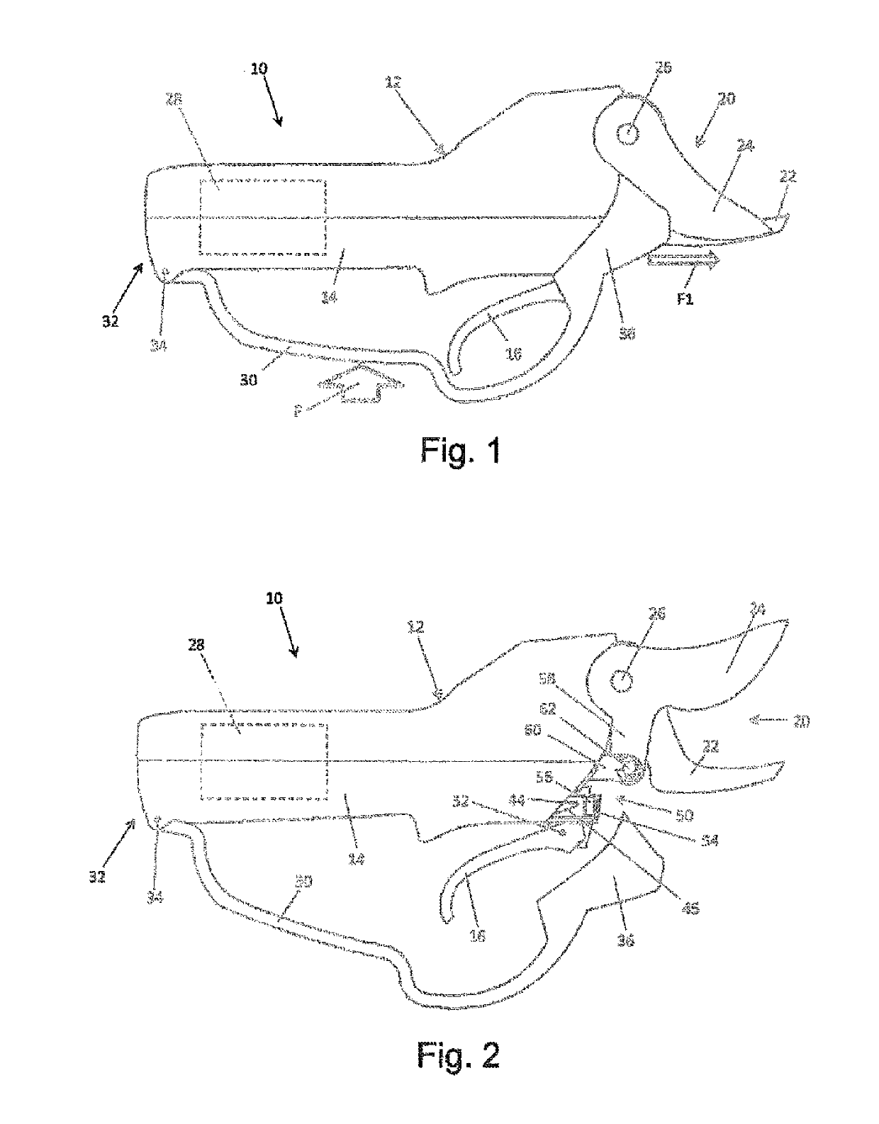
[0032]The following description refers to a specific implementation of the invention for execution of pruning shears. However, and in an entirely similar way, the invention can be applied to other cutting tools, such as hedge trimmers, sheet-metal shears or saws which differ from it essentially in the shape of the cutting member.

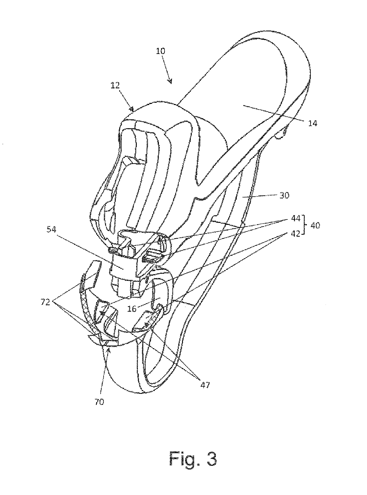
[0033]The pruning shear from FIG. 1 has a tool body 10 comprising a plurality of parts rigidly connected together, essentially by screwing. Among these parts, the figure shows a housing 12.

[0034]The tool body, and more specifically the housing 12, have a substantially cylindrical part forming a handle 14. The diameter of the part forming handle 14 is adapted such that the user can easily grip the tool with their hand.

[0035]The pruning shears from FIG. 1 can also be provided with a remote power unit and a power cord which connect it to the remote power unit. To simplify the figures, these parts are not shown.

[0036]A trigger 16 is located to the front of the h...


PUM

PropertyMeasurementUnit
lengthaaaaaaaaaa
opening thresholdaaaaaaaaaa
movementaaaaaaaaaa

Abstract

A portable motorized cutting tool has a motor housed in a tool body, a cutting member, a transmission linking the motor to the cutting member, and at least one guard for protecting the hand of the user, providing a passage for the hand around at least one of a control member of the tool, and a gripping handle of the tool. The tool has a cover capable of occupying a so-called “closed” position against the body of the tool, and a so-called “open” position separated from the body of the tool and giving access to a part of the tool protected by the cover in the closed position, the cover being linked to the body of the tool by the guard.

Description

TECHNICAL FIELD[0001]The present invention relates to a portable motorized cutting tool and in particular a cutting tool such as pruning shears or sheet-metal shears. The invention can however find applications for other cutting tools and in particular for cutting tools provided with a protective guard for the hand.STATE OF THE PRIOR ART[0002]Various means can be used to provide protection for a user and in particular the hand of a user gripping a cutting tool, and in particular a guard.[0003]The hand of the user grips the tool by a handle or by the body of the handle forming tool. Near the handle, or the part of the tool intended for gripping, a control member of the tool is generally found which is actionable equally by the hand or by a finger while also holding the tool. For some tools, it can simply be a matter of the switch for running or stopping the tool's motor. For other, more sophisticated, tools, it can involve a trigger or a more complex interface controlling one or more...

Claims


Application Information

Patent Timeline
Patent Type & Authority Patents(United States)
IPC IPC(8): B26B29/04A01G3/037B23D29/00
CPCB26B29/04B23D29/005A01G3/037B26B15/00
Inventor PELLENC, ROGER
Owner PELLENC SA
Why Eureka
Try Eureka