
Motion stabilized spotlight

Active Publication Date: 2019-06-04
SPIVAK PAUL
View PDF10 Cites 6 Cited by
  • Summary
  • Abstract
  • Description
  • Claims
  • Application Information

AI Technical Summary

Benefits of technology

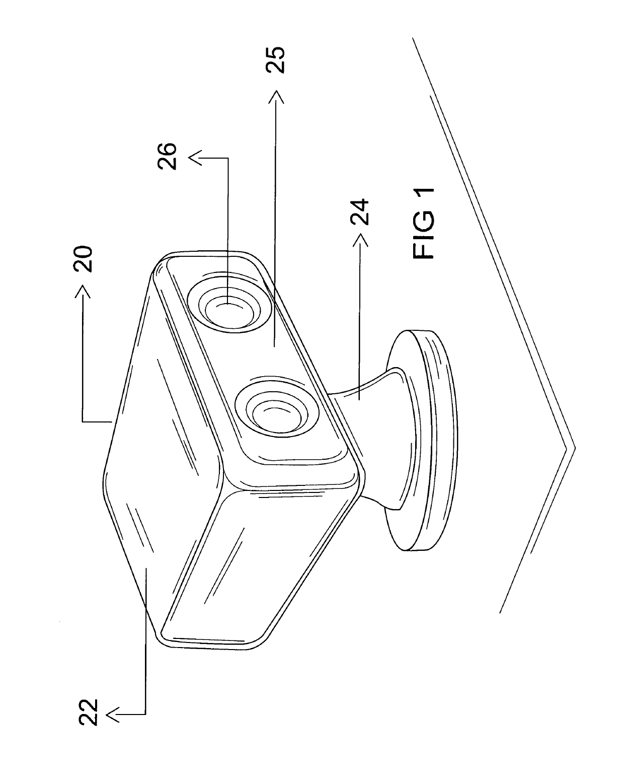
The present invention is a new and improved boat spotlight that can track a specific object, correcting for any movement caused by marine conditions. This allows for smoother and more accurate lighting in the dark.

Problems solved by technology

One long felt problem that remains unaddressed exists when using a spotlight function to target an object when mounted to a moving platform such as a boat.

Method used


Image

  • Motion stabilized spotlight
  • Motion stabilized spotlight
  • Motion stabilized spotlight

Examples


Embodiment Construction

[0025]The best mode for carrying out the invention is presented in terms of its preferred embodiment, herein depicted within the Figures. It should be understood that the legal scope of the description is defined by the words of the claims set forth at the end of this patent and that the detailed description is to be construed as exemplary only and does not describe every possible embodiment since describing every possible embodiment would be impractical, if not impossible. Numerous alternative embodiments could be implemented, using either current technology or technology developed after the filing date of this patent, which would still fall within the scope of the claims.

[0026]It should also be understood that, unless a term is expressly defined in this patent there is no intent to limit the meaning of that term, either expressly or by implication, beyond its plain or ordinary meaning, and such term should not be interpreted to be limited in scope based on any statement made in an...


PUM


Abstract

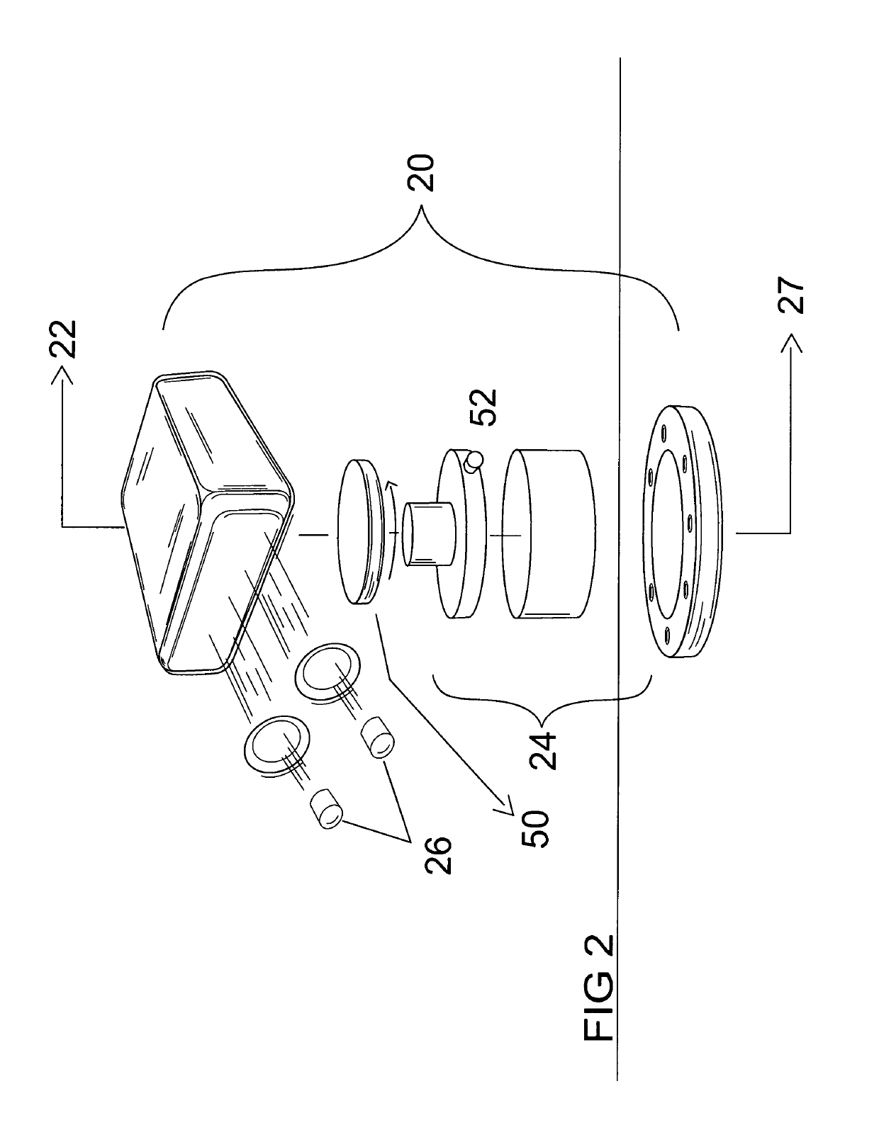
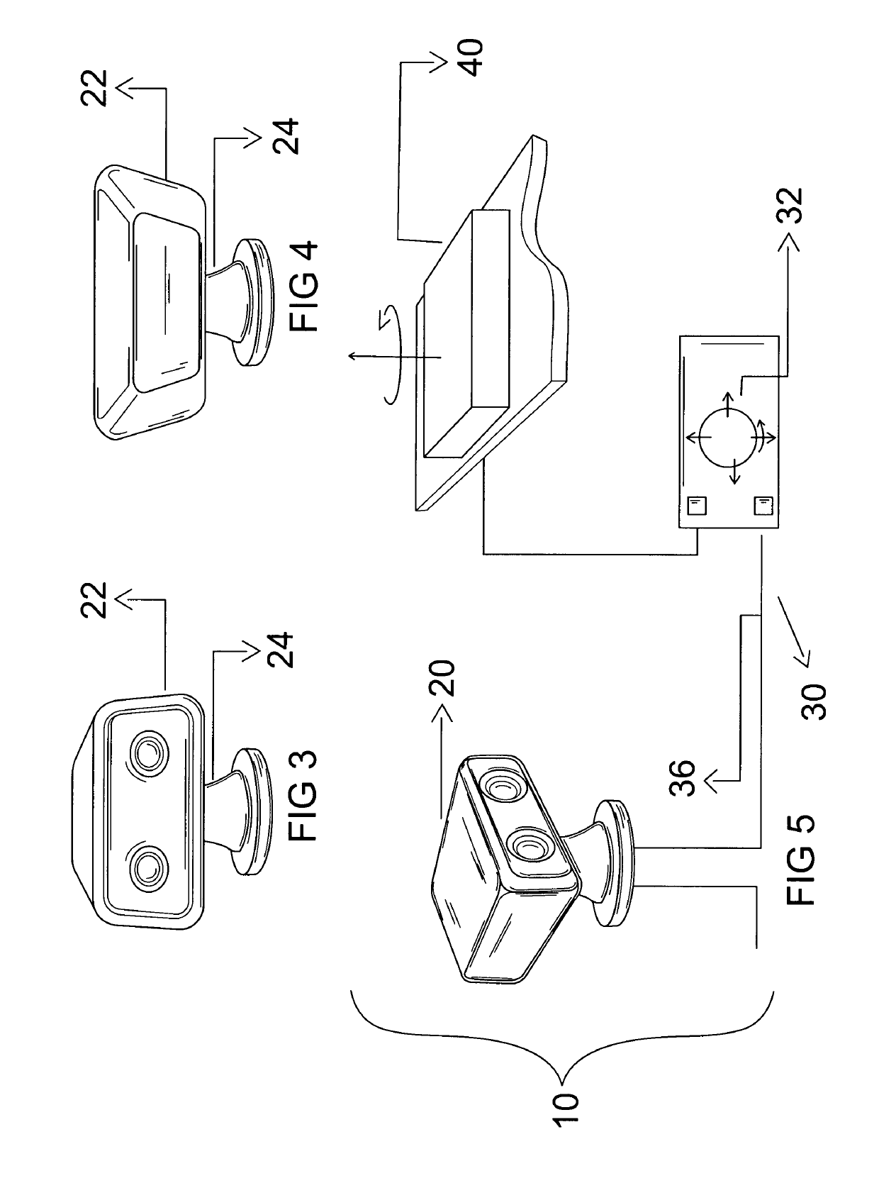
A spotlight apparatus is provided have an illumination element rotationally and pivotally mounted to a pedestal. A vertical control motor urges the illumination housing up and down. A lateral control motor urges the illumination element left or right. A joystick input provides manual directional control of the vertical motor and lateral motor. A MEMS gyroscope or similar microelectronic controller provides an automated control input that, when activated, provides a continuous control signal for providing vertical and lateral motor control based upon a target set point selected by the user.

Description

RELATED APPLICATIONS[0001]There are no previously filed, nor currently any co-pending applications, anywhere in the world.BACKGROUND OF THE INVENTION1. Field of the Invention[0002]The field of invention relates to boat mounting spotlight or searchlight apparatus, and more particularly, to such a boat-mounted spotlight apparatus that is capable of both remote control operation as well as autonomous select target tracking.2. Description of the Related Art[0003]Search lights, spot lights and similar target illumination devices currently exist for use with maritime use. Typical of such lighting arrangements include a pedestal mounted light housing having directional control laterally (usually 360 degree rotation) and vertically (usually + / −45 degrees pivoting from horizontal). In maritime application such lights can have a general use, but are particularly beneficial to target and illuminate objects being approached, either on shore or in or under the water.[0004]Such illuminations syst...

Claims


Application Information

Patent Timeline
IPC IPC(8): B63B45/02F21V21/30F21V21/15B63B49/00G05B15/02G01C17/00B63B45/00F21W107/20F21Y115/10
CPCB63B45/02F21V21/30F21V21/15B63B49/00G05B15/02F21Y2115/10B63B2045/005B63B2213/00F21W2107/20B63B2017/0072B60Q1/245
Inventor SPIVAK, PAUL
Owner SPIVAK PAUL
Learn More