Air bearing assembly for guiding motion of optical components of a laser processing system

a laser processing system and optical component technology, applied in the field of specular processing systems, can solve the problems of particle contamination becoming of greater concern, state-of-the-art structures supporting the laser assembly are too flexible to maintain the required level of precision, etc., and achieve the effect of less motion error, less noise, and higher frequency resonan

Inactive Publication Date: 2008-08-21
ELECTRO SCI IND INC
View PDF13 Cites 28 Cited by
  • Summary
  • Abstract
  • Description
  • Claims
  • Application Information

AI Technical Summary

Benefits of technology

[0008]The massive and structurally stiff substrate isolates and stabilizes the motions of the laser optics assembly and the specimen, absorbs vibrations, and allows for smoother acceleration and deceleration because the supporting structure is inherently rigid. The stiffness of the substrate and close separation of the stage motion axes result in higher frequency resonances, and less error in motion along all three axes. The substrate also provides thermal stability by acting as a heat sink. Moreover, because it is designed in a compact configuration, the system is composed of less material and is, therefore, less susceptible to expansion when it undergoes heating. An oval slot cut out of the middle of the substrate exposes the specimen below to the laser beam and allows for vertical motion of the laser optics assembly through the substrate. Otherwise, the specimen is shielded by the substrate from particles generated by overhead motion, except for the localized region undergoing laser processing.
[0009]A laser beam focal region control subsystem is supported above the lower stage and includes a vertically adjustable optics assembly positioned within a rigid air bearing sleeve mounted to the upper stage by a support structure. The rigidity of the support structure allows for faster and more accurate vertical motion along the beam axis. The inner surface of the sleeve acts as an outer race, and the outer surface of the lens acts as an inner race, thus forming an air bearing guiding the vertical motion of the focal region of the laser beam. Vertical motion is initiated by a lens forcer residing at the top end of the sleeve, which imparts a motive force to the optics assembly to adjust its height relative to the workpiece on the lower chuck, and in so doing, adjusts the focal region of the laser relative to the work surface. An isolation flexure device, rigid along the beam axis and compliant in the horizontal plane, buffers excess motion of the lens forcer from the optics assembly.

Problems solved by technology

In the case in which the laser beam position is continually adjusted, state-of-the-art structures supporting the laser assembly are too flexible to maintain the required level of precision.
Moreover, as circuit dimensions shrink, particle contamination becomes of greater concern.

Method used


Image

  • Air bearing assembly for guiding motion of optical components of a laser processing system
  • Air bearing assembly for guiding motion of optical components of a laser processing system
  • Air bearing assembly for guiding motion of optical components of a laser processing system

Examples


Embodiment Construction

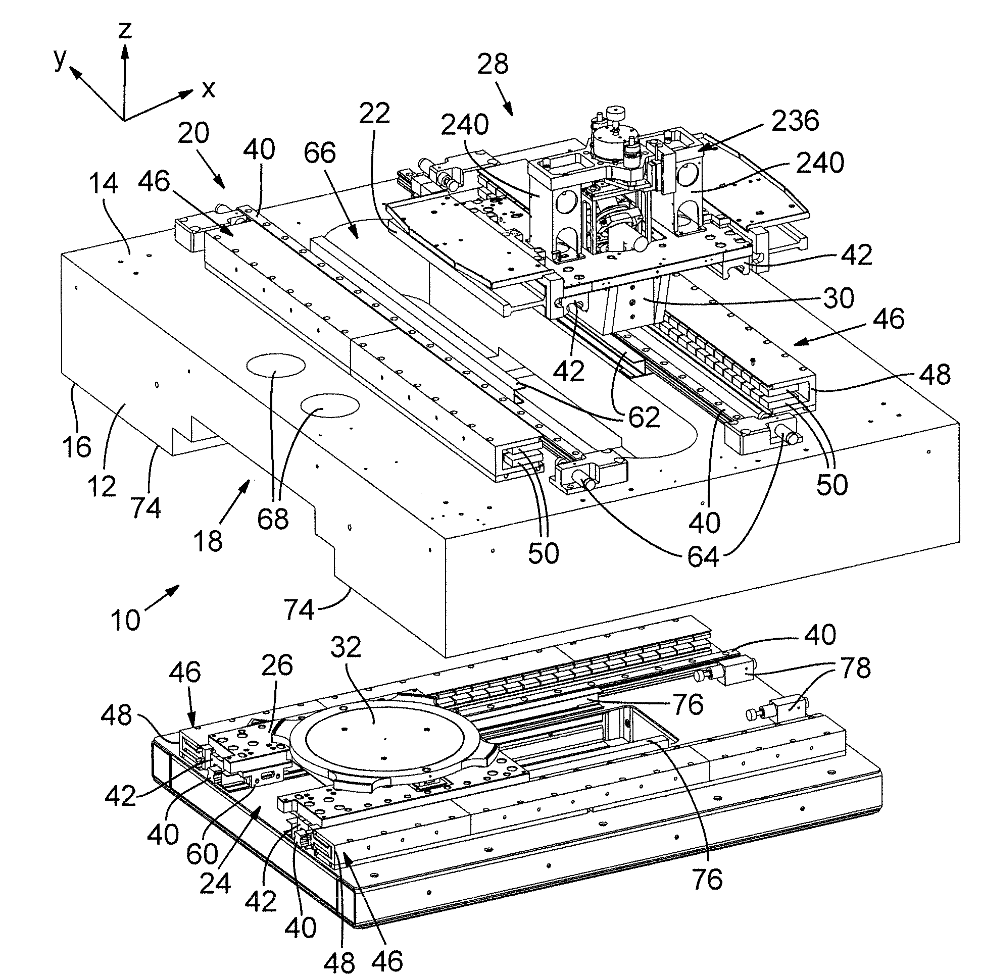
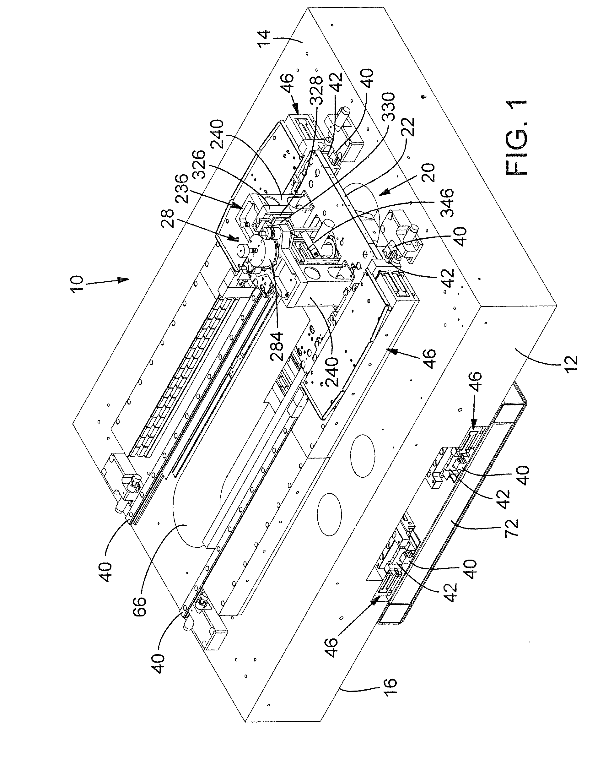
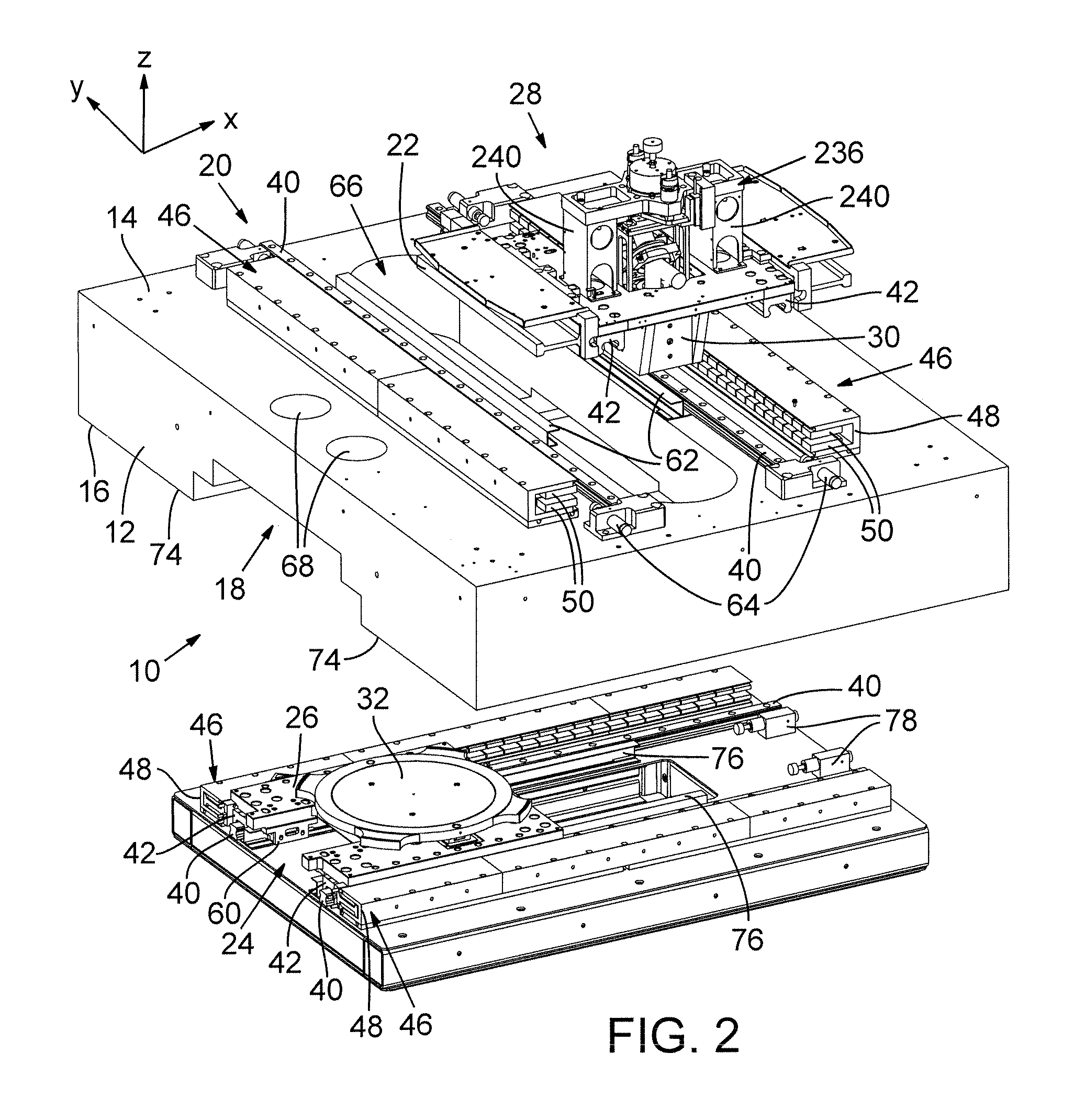
[0018]FIGS. 1 and 2 show a decoupled, multiple stage positioning system 10, which, in a preferred embodiment, supports components of a laser processing system through which a laser beam propagates for incidence on a target specimen. Positioning system 10 includes a dimensionally stable substrate 12 made of a stone slab, preferably formed of granite, or a slab of ceramic material, cast iron, or polymer composite material such as Anocast™. Substrate 12 has a first or upper flat major surface 14 and a second or lower flat major surface 16 that has a stepped recess 18. Major surfaces 14 and 16 include surface portions that are plane parallel to each other and conditioned to exhibit flatness and parallelism within about a ten micron tolerance.

[0019]A surface portion of upper major surface 14 and a first guide track assembly 20 are coupled to guide movement of a laser optics assembly stage 22 along a first axis, and a surface portion of lower major surface 16 and a second guide track asse...


PUM

PropertyMeasurementUnit
flatnessaaaaaaaaaa
motive forceaaaaaaaaaa
outer diameteraaaaaaaaaa

Abstract

A rigid support structure allows for faster and more accurate positioning of axially adjustable optical components in a laser processing system. Vibrational and thermal stability is improved when an optics assembly is housed in a rigid air bearing sleeve that is mounted to a support structure above a specimen stage.

Description

COPYRIGHT NOTICE [0001]©2007 Electro Scientific Industries, Inc. A portion of the disclosure of this patent document contains material that is subject to copyright protection. The copyright owner has no objection to the facsimile reproduction by anyone of the patent document or the patent disclosure, as it appears in the Patent and Trademark Office patent file or records, but otherwise reserves all copyright rights whatsoever. 37 CFR §1.71(d).TECHNICAL FIELD [0002]The present disclosure relates to specimen processing systems and, in particular, to stage architecture for control of two- or three-dimensional positioning of a processing device relative to a target specimen.BACKGROUND INFORMATION [0003]Wafer transport systems configured for use in semiconductor wafer-level processing typically include a stage having a chuck that secures the wafer for processing. Sometimes the stage is stationary, and sometimes it is moveable. Some applications require that the stage move linearly in one...

Claims


Application Information

Patent Timeline
Patent Type & Authority Applications(United States)
IPC IPC(8): G02B7/02
CPCB23K26/0876B23K26/10F16C29/008H01L21/68785F16C32/0603F16C32/0618H01L21/68F16C29/025Y10S33/21
Inventor KOSMOWSKI, MARK T.
Owner ELECTRO SCI IND INC
Why Eureka
Try Eureka